 Here you can select the jobs to be restored or deleted. You can filter your
selection according to a number of different criteria:
• Genesis user name
• Customer name
•Data Repository name
• Date when job was last accessed, backed up, or created
• User-designed custom filter created with the same methods used to
create job filters in the Genesis clipboard.(See Doc. 102, Engineering
Toolkit, for more information on creating job filters.)
Once the list of jobs appears in the display area, you can select only those
jobs that require further processing.
• Select the desired jobs by clicking on the job name.
• Select multiple jobs by holding down the CTRLkey and then clicking
on the job names desired.
You may Select Alljobs that appear in the list by clicking the appropriate
button. Or you may clear the list and start over by clicking Clear All.
Creating a Backup Repository
To create a backup repository:
1. Create a folder in which you will place the configuration and setup files.
Example: C:\genesis\backup.
2. Define a new environment variable, FRONTLINE_BACKUP_DIR, and
then add the path to the backup folder in the variable definition.
3. Inside the backup folder indicated by FRONTLINE_BACKUP_DIR,
insert two new text files bakdblistand bakconfig. Update them according
to the instructions below
New Resize Algorithm
A new algorithm for the Resize operation, introduced in Version 10.0,
eliminates all unexpected behaviors that may occur during Resize
operations. It also improves Fill and Pattern Fill operations.
I/O
Support for Input of New IPC2581A Format
As of version 10, Genesis can support input in the new IPC2581A format.
This is a licensed option - it requires the inp2581license. Data input is
carried out through the standard Import Job function.
Disclaimer
This input was tested only on the sample data provided by the
IPC2581 consortium. Frontline recommends at this stage to ask
customers to send reference data (ODB++ or RS274X) to validate the
input.
Graphic Editor
Interactive Spacing Repair Editor
Introduction
The Interactive Spacing Editorenables you to define spacing
requirements between two selected features at the start of the editing
process, and provides the tools necessary to change one or both features in
order to obtain the desired spacing.
Note If the two selected features touch each other, definition of spacing
requirements cannotbe performed.
There is often a need to resolve interactively spacing problems between
board features. The features could be on the same layer (copper2copper,
clearance2clearance) or on different layers (clearance2copper,
drill2copper, rout2copper). Genesis provides a number of DFM actions to
resolve spacing difficulties, but these DFM actions cannot solve ALL
possible spacing problems, as it would be far too complicated to define
rules that would cover every possible spacing repair problem. A better
solution would be to create automaticDFM actions to solve the majority
of definable spacing problems, and use an interactive tool to repair the
more complex, or less obvious, problems.
Existing Genesis repair tools enable you to move and stretch different
features on a board, but none of these tools enables you to define the
spacing required between features as a starting point of the editing
Here you can select the jobs to be restored or deleted. You can filter your
selection according to a number of different criteria:
• Genesis user name
• Customer name
•Data Repository name
• Date when job was last accessed, backed up, or created
• User-designed custom filter created with the same methods used to
create job filters in the Genesis clipboard.(See Doc. 102, Engineering
Toolkit, for more information on creating job filters.)
Once the list of jobs appears in the display area, you can select only those
jobs that require further processing.
• Select the desired jobs by clicking on the job name.
• Select multiple jobs by holding down the CTRLkey and then clicking
on the job names desired.
You may Select Alljobs that appear in the list by clicking the appropriate
button. Or you may clear the list and start over by clicking Clear All.
Creating a Backup Repository
To create a backup repository:
1. Create a folder in which you will place the configuration and setup files.
Example: C:\genesis\backup.
2. Define a new environment variable, FRONTLINE_BACKUP_DIR, and
then add the path to the backup folder in the variable definition.
3. Inside the backup folder indicated by FRONTLINE_BACKUP_DIR,
insert two new text files bakdblistand bakconfig. Update them according
to the instructions below
New Resize Algorithm
A new algorithm for the Resize operation, introduced in Version 10.0,
eliminates all unexpected behaviors that may occur during Resize
operations. It also improves Fill and Pattern Fill operations.
I/O
Support for Input of New IPC2581A Format
As of version 10, Genesis can support input in the new IPC2581A format.
This is a licensed option - it requires the inp2581license. Data input is
carried out through the standard Import Job function.
Disclaimer
This input was tested only on the sample data provided by the
IPC2581 consortium. Frontline recommends at this stage to ask
customers to send reference data (ODB++ or RS274X) to validate the
input.
Graphic Editor
Interactive Spacing Repair Editor
Introduction
The Interactive Spacing Editorenables you to define spacing
requirements between two selected features at the start of the editing
process, and provides the tools necessary to change one or both features in
order to obtain the desired spacing.
Note If the two selected features touch each other, definition of spacing
requirements cannotbe performed.
There is often a need to resolve interactively spacing problems between
board features. The features could be on the same layer (copper2copper,
clearance2clearance) or on different layers (clearance2copper,
drill2copper, rout2copper). Genesis provides a number of DFM actions to
resolve spacing difficulties, but these DFM actions cannot solve ALL
possible spacing problems, as it would be far too complicated to define
rules that would cover every possible spacing repair problem. A better
solution would be to create automaticDFM actions to solve the majority
of definable spacing problems, and use an interactive tool to repair the
more complex, or less obvious, problems.
Existing Genesis repair tools enable you to move and stretch different
features on a board, but none of these tools enables you to define the
spacing required between features as a starting point of the editing
2013-05-31
Genesis_2000_v10_Frontline_tutorial_download
The new Genesis Backup tool enables you to backup jobs on a network
repository and restore them when you need them. Among other benefits,
this enables you to keep several versions of the same job.
The Backup and Restore functions are part of the Filemenu in the
Engineering Toolkit.
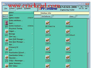 Here you can select the jobs to be restored or deleted. You can filter your
selection according to a number of different criteria:
• Genesis user name
• Customer name
•Data Repository name
• Date when job was last accessed, backed up, or created
• User-designed custom filter created with the same methods used to
create job filters in the Genesis clipboard.(See Doc. 102, Engineering
Toolkit, for more information on creating job filters.)
Once the list of jobs appears in the display area, you can select only those
jobs that require further processing.
• Select the desired jobs by clicking on the job name.
• Select multiple jobs by holding down the CTRLkey and then clicking
on the job names desired.
You may Select Alljobs that appear in the list by clicking the appropriate
button. Or you may clear the list and start over by clicking Clear All.
Creating a Backup Repository
To create a backup repository:
1. Create a folder in which you will place the configuration and setup files.
Example: C:\genesis\backup.
2. Define a new environment variable, FRONTLINE_BACKUP_DIR, and
then add the path to the backup folder in the variable definition.
3. Inside the backup folder indicated by FRONTLINE_BACKUP_DIR,
insert two new text files bakdblistand bakconfig. Update them according
to the instructions below
New Resize Algorithm
A new algorithm for the Resize operation, introduced in Version 10.0,
eliminates all unexpected behaviors that may occur during Resize
operations. It also improves Fill and Pattern Fill operations.
I/O
Support for Input of New IPC2581A Format
As of version 10, Genesis can support input in the new IPC2581A format.
This is a licensed option - it requires the inp2581license. Data input is
carried out through the standard Import Job function.
Disclaimer
This input was tested only on the sample data provided by the
IPC2581 consortium. Frontline recommends at this stage to ask
customers to send reference data (ODB++ or RS274X) to validate the
input.
Graphic Editor
Interactive Spacing Repair Editor
Introduction
The Interactive Spacing Editorenables you to define spacing
requirements between two selected features at the start of the editing
process, and provides the tools necessary to change one or both features in
order to obtain the desired spacing.
Note If the two selected features touch each other, definition of spacing
requirements cannotbe performed.
There is often a need to resolve interactively spacing problems between
board features. The features could be on the same layer (copper2copper,
clearance2clearance) or on different layers (clearance2copper,
drill2copper, rout2copper). Genesis provides a number of DFM actions to
resolve spacing difficulties, but these DFM actions cannot solve ALL
possible spacing problems, as it would be far too complicated to define
rules that would cover every possible spacing repair problem. A better
solution would be to create automaticDFM actions to solve the majority
of definable spacing problems, and use an interactive tool to repair the
more complex, or less obvious, problems.
Existing Genesis repair tools enable you to move and stretch different
features on a board, but none of these tools enables you to define the
spacing required between features as a starting point of the editing
Here you can select the jobs to be restored or deleted. You can filter your
selection according to a number of different criteria:
• Genesis user name
• Customer name
•Data Repository name
• Date when job was last accessed, backed up, or created
• User-designed custom filter created with the same methods used to
create job filters in the Genesis clipboard.(See Doc. 102, Engineering
Toolkit, for more information on creating job filters.)
Once the list of jobs appears in the display area, you can select only those
jobs that require further processing.
• Select the desired jobs by clicking on the job name.
• Select multiple jobs by holding down the CTRLkey and then clicking
on the job names desired.
You may Select Alljobs that appear in the list by clicking the appropriate
button. Or you may clear the list and start over by clicking Clear All.
Creating a Backup Repository
To create a backup repository:
1. Create a folder in which you will place the configuration and setup files.
Example: C:\genesis\backup.
2. Define a new environment variable, FRONTLINE_BACKUP_DIR, and
then add the path to the backup folder in the variable definition.
3. Inside the backup folder indicated by FRONTLINE_BACKUP_DIR,
insert two new text files bakdblistand bakconfig. Update them according
to the instructions below
New Resize Algorithm
A new algorithm for the Resize operation, introduced in Version 10.0,
eliminates all unexpected behaviors that may occur during Resize
operations. It also improves Fill and Pattern Fill operations.
I/O
Support for Input of New IPC2581A Format
As of version 10, Genesis can support input in the new IPC2581A format.
This is a licensed option - it requires the inp2581license. Data input is
carried out through the standard Import Job function.
Disclaimer
This input was tested only on the sample data provided by the
IPC2581 consortium. Frontline recommends at this stage to ask
customers to send reference data (ODB++ or RS274X) to validate the
input.
Graphic Editor
Interactive Spacing Repair Editor
Introduction
The Interactive Spacing Editorenables you to define spacing
requirements between two selected features at the start of the editing
process, and provides the tools necessary to change one or both features in
order to obtain the desired spacing.
Note If the two selected features touch each other, definition of spacing
requirements cannotbe performed.
There is often a need to resolve interactively spacing problems between
board features. The features could be on the same layer (copper2copper,
clearance2clearance) or on different layers (clearance2copper,
drill2copper, rout2copper). Genesis provides a number of DFM actions to
resolve spacing difficulties, but these DFM actions cannot solve ALL
possible spacing problems, as it would be far too complicated to define
rules that would cover every possible spacing repair problem. A better
solution would be to create automaticDFM actions to solve the majority
of definable spacing problems, and use an interactive tool to repair the
more complex, or less obvious, problems.
Existing Genesis repair tools enable you to move and stretch different
features on a board, but none of these tools enables you to define the
spacing required between features as a starting point of the editing
Predator_CNC_Editor_v10_tutorial
Predator MDC v10.0.156 improves all charts with a new Chart Zoom feature via CTRL+Left mouse and pressing the R key to return to the previous view. In addition, the Machine Timeline chart has been significantly improved. Specifically the following improvements have been made:
Improved CSV import support to import commas, double quotes and optional double quotes
Improved Machine Timeline Chart with new command filter
Improved Machine Timeline with new CTRL+Left and CTRL+Right arrow support for next and previous tooltip events
Improved Machine Timeline with better event display and tooltips
Improved My Favorites to honor additional chart options and chart permissions
Improved Event Time Analysis chart to default to drilldown style
Eliminated Trend Analysis chart combinations that are not feasible
Improved MDC APIs to have a v10 specific reference. Non script IDEs need to update to the new MDC API object reference
Improved Splash screen display for specific screen resolutions
Improved upgrade dialog to eliminate virtual network IDs
Improved English, Chinese, Spanish, Japanese, Turkish, Polish, French, German, Italian and Portuguese language resources
Improved online help with additional topics and fixed a number of help IDs
Fixed a bug with function keys and the New Event dialog
Fixed a bug when switching between multiple databases
Predator PDM Enterprise has enhanced the shopfloor dialogs with New Machine Events and Tracker style Check In and Out dialogs. In addition, the following improvements have been made:
 Added -UNRELEASED to change manufacturing and quality status workflow
Improved online help
Improved -viewvaultitem command line to support wildcards
Improved -viewvaultitemdialog command line to support wildcards
Improved machine wizards
Improved the Oracle database login screen
Improved displaying the database name and host within the statusbar
Improved check out warning message
Improved display of LF only style CNC files within the shop floor windows
Fixed a bug with editing a list item
Added -UNRELEASED to change manufacturing and quality status workflow
Improved online help
Improved -viewvaultitem command line to support wildcards
Improved -viewvaultitemdialog command line to support wildcards
Improved machine wizards
Improved the Oracle database login screen
Improved displaying the database name and host within the statusbar
Improved check out warning message
Improved display of LF only style CNC files within the shop floor windows
Fixed a bug with editing a list item
powerbench v3.4.1_tutorial
Fugro-Jason announced today the availability of PowerBench Geology for geological interpretation. This addition to the PowerBench suite was acquired from a large independent oil company that had invested more than 20 years in developing the underlying technology. PowerBench is a Windows®-based application suite for Geology, Geophysics, Petrophysics, and Engineering.
''Geological interpretation is fundamental to providing a single consistent model of the earth,'' said Eric Adams, Managing Director of Fugro-Jason. ''Through this strategic acquisition we were able to add time-tested capability to PowerBench and make that capability available to our customers very rapidly.''
 PowerBench Geology enables unified handling of subsurface geology, well bore equipment and production data. It features an integrated base map and interpretation canvas that handles tens of thousands of wells quickly and efficiently, and a geologic cross section builder that features structural and stratigraphic cross section interpretation. The PowerBench suite encompasses the E&P workflow and includes petrophysical interpretation, seismic and rock property volume interpretation, geologic interpretation, mapping, framework and 3D property modeling, and streamline simulation.
 PowerBench Geology enables unified handling of subsurface geology, well bore equipment and production data. It features an integrated base map and interpretation canvas that handles tens of thousands of wells quickly and efficiently, and a geologic cross section builder that features structural and stratigraphic cross section interpretation. The PowerBench suite encompasses the E&P workflow and includes petrophysical interpretation, seismic and rock property volume interpretation, geologic interpretation, mapping, framework and 3D property modeling, and streamline simulation.
Mastercam_x7_v16.05_crack_tutorial
Mastercam X7 also includes Mastercam Mill-Turn, designed to simplify programming for complex Mill-Turn machines.
IMPORTANT If you are interested in purchasing this product, please contact your local Mastercam reseller.
The centerpiece of Mill-Turn is the Code Expert application. Like the new Tool Manager, the Code Expert runs in the new Extensions window. Code Expert incorporates an entire suite of tools for managing multitasking applications.
Mastercam is known for powerful NC programming. But it also delivers a suite of shop-tested design tools including 3D surfacing and solids.
Click on the above tabs for a quick overview of CAD choices. Or choose from the buttons on the right for more detailed information.
What does this mean for you? It means that when you choose Mastercam, you’re using innovative CAM software that has helped more shops achieve success than any other. It also means that skilled Mastercam users are much easier to find.
Mastercam’s Support is Second to None
Mastercam is supported by a worldwide network of dedicated, expert resellers who focus exclusively on ensuring that Mastercam fits your needs. They know the software, know your area, and are there when you need them.
 Mastercam also enjoys a large online user community that offers advice, help, tips and tricks to fellow Mastercam programmers.
Mastercam is Dedicated to the Future
As one of the pioneers in PC-based CAD/CAM, Mastercam has a long history of company security and health. As a privately-owned company, we continue to focus exclusively on the needs of NC programmers. And as a CAD/CAM innovator, we’ll be here to work with you as you move into the future.
Mastercam also enjoys a large online user community that offers advice, help, tips and tricks to fellow Mastercam programmers.
Mastercam is Dedicated to the Future
As one of the pioneers in PC-based CAD/CAM, Mastercam has a long history of company security and health. As a privately-owned company, we continue to focus exclusively on the needs of NC programmers. And as a CAD/CAM innovator, we’ll be here to work with you as you move into the future.
SDS/2-v7.313-Design-Data-download-crack
SDS/2 Detailing offers the highest level of automation and intelligence available in 3D steel detailing.
As the detailer inputs members, like columns and beams, connections are automatically designed with their necessary materials, bolts, holes and welds. SDS/2 Detailing takes a uniquely intelligent approach in its connection design by considering framing conditions and erectibility, automatically performing clash prevention as a part of its connection design. In addition, SDS/2 Detailing can value engineer the connections on a project, helping users to design the most economical connections to fabricate and erect. No other 3D detailing product can do this automatically.
SDS/2’s expanded design calculations give users the full formulas for all force checks of connections. With SDS/2, users can see how the software arrives at the connection results, and assists engineers in reviewing
 SDS/2 Approval supports AISC's methodology for model approval by allowing communications like sketches, addendums and RFIs, as well as status updates, to be stored and exchanged via the 3D model. Whether you choose to approve models on a project using the Hybrid method of the Full Model Approval method, there is an SDS/2 solution that supports either approach.
The free SDS/2 Viewer allows the model to be used as a supplemental tool to more easily verify drawings. From the model, engineers can view information during the approval process, like connection design calculations, material information, member status and more.
Using SDS/2 Approval, engineers can receive submittals via the model, and then use it to approve, reject or note changes to be made. They can then transmit that information back to the detailer or fabricator's model via tools provided by SDS/2 Approval.
SDS/2 Approval supports AISC's methodology for model approval by allowing communications like sketches, addendums and RFIs, as well as status updates, to be stored and exchanged via the 3D model. Whether you choose to approve models on a project using the Hybrid method of the Full Model Approval method, there is an SDS/2 solution that supports either approach.
The free SDS/2 Viewer allows the model to be used as a supplemental tool to more easily verify drawings. From the model, engineers can view information during the approval process, like connection design calculations, material information, member status and more.
Using SDS/2 Approval, engineers can receive submittals via the model, and then use it to approve, reject or note changes to be made. They can then transmit that information back to the detailer or fabricator's model via tools provided by SDS/2 Approval.
Subscribe to:
Posts (Atom)
