2012-08-23
ShipConstructor-2012-download
ShipConstructor is an AutoCAD based shipbuilding CAD/CAM software suite that provides detail design and modeling tools for production engineering of marine structures. ShipConstructor captures all information relevant to the 3D design, manufacturing, maintenance, repair and refit of complex marine projects inside of a Marine Information Model (MIM). At the heart of the model is a single relational database residing on a Microsoft SQL Server that can be integrated with related business processes and applications. ShipConstructor’s unique software architecture and AutoCAD foundation provide significant competitive advantages.
ShipConstructor 2012 R2 reduces the time needed to clearly and cleanly label drawings through various improvements in labeling. The convenience and speed of manual labeling has been increased by providing manually activated options for automatic redistribution of label bubbles along label leader distribution lines using Center, Nearest, or Equidistant placement while automatically preventing leader lines from crossing. Meanwhile, rework is prevented since ShipConstructor 2012 R2 now preserves user-chosen setups of labels and leader distribution lines without being overridden.
New commands further improve clarity by allowing the consolidation of close or similar angled leader distribution lines. This function is particularly useful in production drawings where parts are labeled from multiple BOM tables.
The Subscription Advantage Pack for ShipConstrurctor 2012 R2 (scheduled for launch in April 2012) will also include the ability to automatically label to the edge of a part rather than the piecemark. This highly requested feature allows more efficient generation of production drawings to comply with common industry requirements
ShipConstructor 2012 R2 introduces the ability to model Electrical Cable Supports within Space Allocations. This enhancement will also support the Electrical Module Cable Routing feature when it is released. Cable Supports provide an equipment style of modeling inverted tee, trapeze, tray, tray supports, and other types of cable supports. Any type of stock may be defined to have multiple standard drawings per stock in order to represent different configurations and interval spacing of the same stock in order to simplify management. Flexible tools to easily allow the renaming of cable supports have been introduced as well.
Two new drawing types are available to host the Cable Supports objects:
Wireway model drawing - a unit bound drawing for modeling space allocations and cable supports
Wireway arrangement drawing - a general electrical production drawing
CST-Studio-Suite-V2012-sp4crack
The electromagnetic simulation software CST STUDIO SUITE® is the culmination of many years of research and development into the most accurate and efficient computational solutions for electromagnetic designs. It comprises CST’s tools for the design and optimization of devices operating in a wide range of frequencies - static to optical. Analyses may include thermal and mechanical effects, as well as circuit simulation.
CST STUDIO SUITE benefits from an integrated design environment which gives access to the entire range of solver technology. System assembly and modeling facilitates multi-physics and co-simulation as well as the management of entire electromagnetic systems.
CST STUDIO SUITE can offer considerable product to market advantages such as shorter development cycles, virtual prototyping before physical trials, and optimization instead of experimentation.
CST STUDIO SUITE comprises the following modules:
CST MICROWAVE STUDIO® (CST MWS) is the leading edge tool for the fast and accurate 3D simulation of high frequency devices and market leader in Time Domain simulation. It enables the fast and accurate analysis of antennas, filters, couplers, planar and multi-layer structures and SI and EMC effects etc.
CST EM STUDIO® (CST EMS) is an easy-to-use tool for the design and analysis of static and low frequency EM applications such as motors, sensors, actuators, transformers, and shielding enclosures.
CST PARTICLE STUDIO® (CST PS) has been developed for the fully consistent simulation of free moving charged particles. Applications include electron guns, cathode ray tubes, magnetrons, and wake fields.
CST CABLE STUDIO™ (CST CS) for the simulation of signal integrity and EMC/EMI analysis of cable harnesses.
CST PCB STUDIO™ (CST PCBS) for the simulation of signal integrity and EMC/EMI EMI on printed circuit boards.
CST MPHYSICS STUDIO™ (CST MPS) for thermal and mechanical stress analysis.
CST DESIGN STUDIO™ (CST DS) is a versatile tool that facilitates 3D EM/circuit co-simulation and synthesis.
To learn more about the licensing options of CST STUDIO SUITE 2012, please refer to our Terms & Conditions.
CST MICROWAVE STUDIO® (CST MWS) is a specialist tool for the 3D EM simulation of high frequency components. The unparalleled performance of CST MWS makes it the first choice in technology leading R&D departments.
CST MWS enables the fast and accurate analysis of high frequency (HF) devices such as antennas, filters, couplers, planar and multi-layer structures and SI and EMC effects. Exceptionally user friendly, CST MWS quickly gives you an insight into the EM behavior of your high frequency designs.
CST promotes Complete Technology for 3D EM. Users of our software are given great flexibility in tackling a wide application range through the variety of available solver technologies. Beside the flagship module, the broadly applicable Time Domain solver and the Frequency Domain solver, CST MWS offers further solver modules for specific applications. Filters for the import of specific CAD files and the extraction of SPICE parameters enhance design possibilities and save time. In addition, CST MWS is embedded in various industry standard workflows through the CST design environment.
2012-08-17
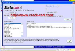
MasterCam-X6-MU2-crack
Mastercam X6 Release Highlights
Mastercam X6 delivers full 64-bit support and a powerful set of new tools to help you make the most of your shop. We've listed some highlights below (click the video icon to see a quick demonstration):
Mill and Router:
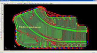
The new in-process stock model delivers an accurate representation of your part as toolpaths are applied to it. The model can be verified and used as the basis for additional toolpaths. video
Enhanced dynamic milling includes finer control and additional time savings. video
Fast 2D HST region chaining dramatically speeds up dynamic toolpath programming. video
Smart rest roughing uses the new in-process stock model to create a highly efficient pass to remove stock remaining from a larger tool
Hybrid finish "filler" passes divide your part into a series of Z sections and applies two different machining strategies to each section for a superior finish.
Lathe:
Variable depth roughing for longer insert life. video
Easy pick, pull and cutoff operations. video
Remaining stock removal. video
Smart finishing that identifies and cuts flats and walls with different motion. video
Finish tool inspection. video
Enhanced canned rough and finish toolpaths.
New finish feed / speed facing and canned grooving controls.
Wire:
Enhanced autosyncing.
Improved wirepath editing.
New force wire taper to vertical options.
CAD Tools:
Finer control over intersecting and trimming solid edges.
Enhanced solid trim to surface.
Dynamic transform along a vector.
Blade Expert: video
With the release of Mastercam X6 , we're also introducing Mastercam Blade Expert, a new purchasable add-on designed for multi-bladed parts. This powerful tool can be added to Mastercam Mill Level 3 or Router Pro, and delivers:
Powerful programming for fans, propellers, impellers, turbines, marine screws and more.
Variety of efficient roughing strategies.
Precise curt pattern control on blade, fillet, and floor finishing.
Automatic tool axis control.
Full machine simulation.
These enhancements and updates have been tested and released by the Quality Control Department and will function inside Mastercam X6. Follow the instructions given in the 'info' button of each download for install instructions.
Read Before Installing Mastercam X6
X6 has both a 32bit and a 64bit version so please read the notes below:
The X6 32bit version can only be installed on a 32bit OS and the X6 64bit version can only be installed on a 64bit OS.
X6 64-bit version will NOT allow saving to a previous X version.
X6 32-bit can save files to previous version just as past versions allowed (geometry only).
Files created in previous Mastercam versions can be read into both X6 32 and X6 64 bit versions.
The X6 64-bit version is installed into the C:\Program Files. X5 was installed into the C:\Program Files (x86) folder on 64bit OS systems because it was a 32bit application.
There is only one set of sample files and power libraries and they will work with both x64 and x86.
Art is only available for 32-bit operating systems. The 64-bit version is currently in development.
CAM-TOOL-V7.1
Sophisticated NC programmers appreciate the importance of a complete, integrated CAD/CAM environment to handle the toughest manufacturing jobs. Regardless of the application, these ELITE users often find the need to modify, edit & create additional geometry to support the creation of toolpath.
compatible with Windows XP, XP64, VISTA, and Windows 7 X64 Professional, CAM-TOOL provides Mold & Die manufactures a wide range of modeling capabilities not found in "high end" programming systems. Once your data's prepared, the calculation of NC toolpath is completed by simply defining your machining strategy & cutting tools. CAM-TOOL does the rest by always making sure the tool only goes where necessary to remove material using our powerful optimization capabilities.
Graphic Products Inc. has a proven track record in data conversion. With over 20 years of technical expertise in the software industry, CAM-TOOL’s data translators provide robust, accurate and reliable data conversion. Conversion capabilities include translators able to handle most data types including but not limited to: Input and Output formats for IGES (JAMA-IS compatible), DXF, CAM-TOOL.C3. Optional direct translator support is provided for CATIA and UNIGRAPHICS. Standard output from CAM-TOOL Base Module is RPS (STL and RPF are optional).
[Main Functions]
Input/ Output formats in CAM-TOOL:
IGES (JAMA-IS compatible)
DXF
CAM-TOOL.C3
Direct Translator support for: CATIA* UNIGRAPHICS* (Parasolids)
Output Formats from CAM-TOOL: RPS (Standard) STL* RPF*
*Optional Items: RPS is Standard in the Base Module.
SHAPE DIAGNOSIS
- Geometry Evaluation -
Geometry Evaluation and editing functions are integrated into the modeling function for use in die/mold design. This powerful tool is used to create die/mold surfaces from product models and also provides valuable information about the model such as Radius and Draft Angle.
In the past, the process of developing mold models from product models was a time consuming process. When developing CAM-TOOL, attention was focused on this previously inefficient area in order to develop a more practical geometry evaluation function. A variety of advanced capabilities were created including such functions as cavity/core split, undercut, draft angle and volume surface area calculation. These functions relieve the designer/operator from tedious, demanding and intricate work.
Display of Fillet Radius Data of Specified Surfaces
Fillet Radius extraction using specified surfaces and single-operation processing. Accurate shape control by cross-section line extraction.
Display of Draft Angle Data at Specified Surfaces
Extraction of surfaces on vertical walls in one operation. Surfaces for which the tilt is smaller than the specified draft angle, can be extracted in one operation. Since the system selects the necessary surfaces directly, the designer/operator can switch to editing operations immediately.
[Main Functions]
Automatic extraction of non-frontal surfaces.
Cavity/core split.
Undercut - Yes / No
Draft Angle data.
Volume and surface area calculation.
Maximum co-ordinate (boundary) values for surfaces.
Extraction of surfaces on vertical walls.
Extraction of cross-section.
MODELING
- Die/mold Surface Design - CAM-TOOL‘s modeling functions are designed specifically for the demands of die/mold surface design. The array of fillet and surfacing functions are easy to use and master. Consequently, the sophisticated modeling required for the direct cutting of cavities can be accomplished more efficiently.
Worknc-G3-V21
WorkNC is best of breed, complementary CAM software that enhances all design and manufacturing systems by providing the most reliable, efficient, easy-to-program cutter paths, resulting in unmatched productivity and safety.
The automatic features of WorkNC allow novice CAM operators to automatically set up toolpaths in just a few minutes. Experienced users of other CAM software quickly appreciate the profitable and unique benefits WorkNC provides. Used either directly on the shop floor or in your CAD room, the reliability and quality of WorkNC's CNC programming are unsurpassed!
Automatic CAD CAM for 2 to 5 axis
TRANSFORM YOUR SHOP’S EFFICIENCY WITH V21!
WorkNC V21 is the latest release of WorkNC and the first release to support task threading and parallel processes on multi-core processors. What does this mean for WorkNC users?.....
* Task Threading: certain cutterpaths will now run multiple threads. That means individual portions of the cutterpath will be calculated at the same time. Computers with multi-core processors will run those threads individually, on separate cores, decreasing calculation times. It is not just cutterpaths that can be multi threaded, but other calculations as well. For example, Auto 5 will be able to take advantage of this technology for faster calculations.
* Parallel Processes: multiple cutterpaths in the workzone can be run simultaneously, as long as one is not dependant on another. For example, a Planar Finishing can run at the same time as a Z-Level Finish, since one is not dependant on the other. However, a Global ReRough may need to wait on a stock model update before calculations start. Parallel processing will allow you to calculate more cutterpaths faster than ever before, taking advantage of your multi-core processors.
Video tutorial - WorkNC parallel calculation window
In addition to multi-core support, WorkNC V21 includes other new features such as:
* Support for 64 Bit Windows
* Continuous Finishing - a complete new finishing algorithm.
* Enhancements to Auto 5 (module that automatically converts 3 axis into 5-axis simultaneous toolpaths).
* Various enhancements to 3-axis cutterpaths.
* Fast Machine and holder collision checking.
* Calculation of maximum collision free regions on tool holders
* New, highly automated, view creation options
* Numerous, intelligent enhancements to the GUI
DNV-Sesam-2011-tutorials
Sesam GeniE
is a tool for designing and analyzing offshore and maritime structures made of beams and plates. Modelling, analysis and results processing are performed in the same graphical user interface. The use of concept technology makes Sesam GeniE highly efficient for integrating stability, loading, strength assessment and CAD exchange. All data are persistent enabling the engineers to do efficient iterative re-design of a structure.
Sesam GeniE for fixed structures
The analysis – hydrodynamic as well as strength calculations – and evaluation of results are done within GeniE. GeniE is built for frequent changes in both structural and equipment layout – any modification performed on a concept level will give an automatic updated and consistent analysis model.
For fixed platforms, GeniE can perform static and dynamic linear analysis for structures subjected to wave, wind, current and the equipment layout. It is also possible to include the effects from non-linear pile/soil behaviour. Code compliance of beams may be performed according to API/AISC, API/LRFD, Norsok/Eurocode or ISO (19902). The results may be reported graphically or by using standard report layouts that can be customized (supporting MS Office). Similarly, for plated structures (stiffened as well as un-stiffened) they may be checked against codes like DNV (RP C201.1) and API(2U).
Sesam HydroD
is a tool for hydrostatic and hydrodynamic analysis. By integrating these tasks significant cost savings may be achieved in the engineering phase since the same panel model may be used by one tool.
Sesam HydroD will perform compliance checks against statutory rules for stability including the importance of integrity of the deck tanks. Floating positions may be determined as a result of actual mass and buoyancy or from an automatic compartment filling to satisfy specified position.
Hydrodynamic analysis
The hydrodynamic analysis may be performed using the actual floating position – and independent of the panel model – to determine worst loading conditions to be used in structural strength analysis. These analyses are normally performed in the frequency domain, but it is also possible to do it in time domain (Linear as well as non-linear).
The loads (pressure and accelerations) are automatically used by the structural analysis. The response and loads may be graphically assessed in animations.
Sesam DeepC
is a tool for mooring and riser design as well marine operations of offshore floating structures. It will perform mooring analysis separately or when including the coupled effects from risers and vessels. Furthermore, Sesam DeepC may be used for riser design where the risers are analyzed separately or when considering coupling effects. Marine operations may be simulated in the time domain for a study of motions and station keeping of multibody systems.
For deep water installations, the riser and mooring systems greatly influence the motions of the floater. The floater and slender structures constitute an integrated dynamic system responding to the environmental loading. Because coupling effects are consistently treated, there is no need for the engineers to make assumptions about the damping level (updated for each time step) which is crucial in a non-linear analysis accounting for slender structure restoring, damping and inertia forces. In other words, Sesam DeepC will increase the confidence level of riser and mooring analysis.
SDS/2-v7.3-Design-Data-download
SDS/2 Engineering combines connection design with 3D frame analysis and member design, all neatly packaged for use as an accurate BIM model. No other engineering product can offer the model accuracy and time savings of SDS/2 v7.3 Engineering.
Unlike other frame analysis products, SDS/2 Engineering creates a model that is accurate to manufacturing standards, with correct top-of-steel elevations and work point locations — enabling connections to be automatically designed while considering both fit-up and constructability. Another feature unique to SDS/2 Engineering is the ability to calculate transfer forces while designing the structure — translating to safer connections and safer structures.
Continuous changes are a staple of almost every project. SDS/2 Engineering handles these changes quickly, completely and with ease. In any change, such as layouts, member sizes, or loads, SDS/2 Engineering will reanalyze the frame, resize members, and redesign connections automatically.
As the number of engineering firms that include shop drawings as a part of their deliverables grow, SDS/2 Engineering will become increasingly valuable as an engineering tool. It shares the same 3D database with all other SDS/2 software solutions, providing a seamless bi-directional transfer of information. Engineers can use SDS/2 Engineering to analyze a model created by any SDS/2 software, or detailers can use SDS/2 v7.3 Detailing to create shop drawings directly from the model created with SDS/2 Engineering. Either way, time and expense are saved and the probability of errors is significantly reduced. At any time, users can export their model to — or import a model from — their collaborative BIM product of choice.
Together, SDS/2 software solutions connect contractors, engineers, detailers, fabricators and erectors in a collaborative work process.
2012-08-14
Neotec_PIPEFLO_9.0.2_CRACK
PIPEFLO V9 is a steady state simulator for flow assurance issues.
PIPEFLO’s features for sensitivity studies make it fast and easy for users to consider a wide variety of options in order to arrive at the best solutions for their design issues and operational problems.
Flow Assurance
Pipeline Design
Automatic Facility Locator
Advanced Sensitivity Studies
Export to OLGA
Hydrates
Corrosion
Pipeline Optimisation
Pipeline Cool Down Calculation
Pipeline Looping
Solution include
Designing a water distribution network for an enhanced oil recovery project
Sizing pipelines in a two-phase heavy oil system
Predicting and locating corrosion potential in a sour gas pipeline
Designing the facility requirements to maintain acid gas in the liquid phase in a disposal operation
Locating compressor stations in a gas transmission line
Analysing gathering systems that include fibreglass or PVC line
Designing heat tracing for a liquid sulfur line
Expanding steady-state slugging studies to include transient modelling via a link with OLGA® for flow assurance in offshore pipeline systems
PIPEFLO Dynamic is the solution that brings dynamic simulation into the existing steady-state workflow and allows users to model select dynamic operations in conjunction with their standard steady-state modelling.
Accessible through PIPEFLO’s proven interface, PIPEFLO Dynamic is powered by OLGA® to allow the seamless application of consistent steady-state and dynamic flow modelling. A limited set of data entry is required in addition to what is already required for a typical steady-state flow model. The level of integration promotes significant time and cost savings and powerful workflow efficiencies.
Fugro_Jason_8.3_DOWNLOAD
Jason® brings together petrophysics, modeling and reservoir seismic inversion to solve the most compelling exploration & production challenges.
Unconventional shale gas—define the best drilling and frac program
Thin reservoirs—locate and tap them most effectively
Complex reservoirs—unravel tuning and AVO effects to map the true geologic character of the reservoir
Fugro-Jason V8.3, the leader in reservoir characterization technology for the oil and gas industry, today announced the release of version 8.3 of Jason™ reservoir characterization software. Jason™ brings the most advanced technology to the geoscientist’s desktop with new functionality particularly suited for managing assets in challenging environments such as shale oil plays and shale gas plays, thin bed reservoirs and subsalt formations.
Jason addresses a wide variety of geologic settings and challenges with powerful geostatistical reservoir characterization; wavelet estimation and well to seismic ties; and 2D and 3D seismic inversion. In shale oil and shale gas plays, Jason can play an important role in building an effective hydraulic fracturing program. Significant enhancements in geostatistical reservoir characterization improve detail in areas where reservoir formations are vertically thin and difficult to detect and correlate.
Fugro-Jason’s flagship suite of integrated applications helps geoscientists find the best pay zones and visualize how the reservoir connects across the field. Adams adds, “Our mission is to provide our customers with the clearest view of their subsurface reservoir as possible. Jason software helps operators not only understand risk, but reduce it in the process.”
The Jason® software suite includes solutions for Petrophysics and Rock Physics, Interpretation and Analysis, Model Building, Seismic Inversion and Geostatistical Inversion. Using these tools in an integrated fashion, you can perform Seismic to Simulation studies using highly accurate and predictive reservoir models to evaluate alternate management strategies and predict future production and ultimate recovery from your field.
Zuken_CR5000_Board_Designer_v13_CRACK
CR-5000, Zuken’s advanced PCB design software, offers highly sophisticated functionality for the layout of multi-layer high-speed PCBs and IP packages, addressing design challenges such as signal integrity, power integrity and EMC, while ensuring high-yield manufacturability.
CR-5000
CR-5000: PCB design software - PACKSHOT THUMBNAIL
Enterprise-wide PCB Design
Ensures integrity of PCBs throughout design and manufacturing through a constraint-driven design process with concurrent DFM verification
Facilitates highly sophisticated product design - covering multi-layer and high-speed package and PCB technology, with integrated signal integrity and EMC analysis
Created to serve medium to large organizations conducting multi-user design
Zuken’s CR-5000 Board Designer is an intuitive, integrated environment for designing PCBs, BGAs and MCMs. With support of 3D utilities and viewers for HDI and advanced packaging, Board Designer offers one solution for all board technology needs.
CR-5000 enables an interactive workflow between logical circuit engineering and board layout. CR-5000’s placement and routing tools are optimized for speed and accuracy, enabling you to tackle today’s complex PCB design challenges.
YDC_Cadvance_αⅢ_V5.X_crack
YDC Corporation is a Japan based system integrator. The company is engaged in the provision of the CAD system for electronic design. It offers various products such as CADVANCE aIII series which supports schematic design, PCB design, and parts information management; CADVANCE aIII-Eye series which solves the problems among heterogeneous CAD tools and improve productivity; and CADVANCE aIII-Design Server for simultaneous concurrent design which reduces the design time dramatically. In addition, it offers YDC SONAR, which is the solution for Visualization of the fab to support the needs for every staff from line managers to process engineers. YDC SONAR provides several running environments from small configurations for test line with various users to broad BI(Business Intelligence) tool to monitor whole fab according to user needs and purposes, as well as offers unique database structure, and GUI that is specialized and ideal for semiconductor and FPD manufacturing process. The company is headquartered in Fuchu-shi, Tokyo, Japan.
CADVANCE aIII series
CADVANCE αⅢ-EyeDesign
CADVANCE AlphaIII-Design
CADVANCE αⅢ-EyeSchema
CADVANCE αⅢ-Schema
CADVANCE αⅢ-FileMaster
YDC offers the CAD system for electronic design that meets the needs of the customer's eternal theme in electronic design, that is, "time to the market, high quality, and high reliability".
"CADVANCE", which was developed first in 1982 spending all one's energy of the YOKOGAWA group, is the CAD system that has been enhanced to meet a large number of requests from the customers and to support the latest technologies for many years since its first release.
YDC provides the following products as solution to make the design environment optimized to the customer's needs.
CADVANCE αIII series that support schematic design, PCB design, and parts information management
CADVANCE αIII-Design Server for simultaneous concurrent design that reduces the design time dramatically
CADVANCE αIII-Eye series that solve the problems among heterogeneous CAD tools and improve productivity in all stages of design, checking of drawing, analysis, manufacturing, and inspection
Knowing the essence of manufacturing even as for every corner and true needs of the customer, we offer the design environment for new electronic designs at our customers that are used as not only the design tools but also the environment to share the information among the collaboration sites connecting the person with the person, the person with the enterprise, and the enterprise with the enterprise and the simultaneous concurrent design environment to work with the foreign countries.
GeoTeric_v2012.1_download
Interactively extract accurate, multi-layered geological expressions from your data for
faster geological insight.
Power-on with GeoTeric™ to bridge the gap between processing and 3D interpretation, by directly translating geophysical data into the geological expressions of
shale, salt, carbonates, clastic and structure.
Learn more about the technology that has powered the success of over 300 projects in conventional and unconventional reservoirs for over 100 E&P companies worldwide - and how you can reach the most informed, seismically driven decisions you've ever made.
Tile group Shale
Connect with high-precision localisation in clastic systems
Uncover the full potential of your seismic data to identify untapped potential and extend the productive life of your field.
Use GeoTeric to capture geological expressions from all available seismic data rapidly, accurately and objectively. Identify and extract geological details with high-resolution information on facies changes and reservoir heterogeneity to examine previously worked regions in greater detail and to de-risk new hydrocarbon plays.
Construct more accurate geological models with interpreter-guided, data-driven 3D geometries, highlighting potential reservoirs and surrounding geological entities, leading to more realistic recovery estimation and greater confidence in well planning.
Secure sharper carbonate reservoirs definition and estimation
Better understand reservoir geometry, heterogeneity and inter-connectivity for effective production from carbonate plays.
Improve depositional modelling of carbonates with accurate facies classification. Identify fault corridors to assess fluid flow and production potential.
Create 3D representations of dissolution features to understand extent and connectivity throughout the reservoir, significantly reducing drilling risk.
GeoTeric helps you improve well planning and placement by rapidly identifying variations in fracture density that are almost impossible to recognise with conventional interpretation.
Access rapid, accurate salt boundary delineation
With advanced noise attenuation, GeoTeric makes sub-salt seismic events easier to map, revealing intricate geological changes that can indicate potential hydrocarbons.
Quickly detect finer variations in seismic signature – invisible to the naked eye – and delineate the complex faulting often associated with salt movement more objectively than ever.
Feed your salt body and structural results back into the workflow, bringing together the many insights extracted from your data, for a complete picture of geological structure and a more accurate reservoir model.
Image: Processed on Netherlands TerraCubeREGRID TM data, supplied by
Fugro Data Services AG.
SPT_GROUP_MEPO_V4.0_Download
Multiple Realisations for Robust Prediction of Reservoir Performance.
MEPO is a step change in the reservoir engineering workflow. It substantially enhances the value you will get from your existing reservoir simulation models, by enabling a "multiple realisation" approach – allowing you to not merely model your reservoir, but to optimise it for maximum performance. MEPO can be used to improve your reservoir decisions in a number of areas – from determining the best locations for infill wells, to selecting the optimal development scenario, understanding uncertainty, or semi-automating laborious tasks such as history matching. Best of all, it works in harmony with your existing reservoir simulator, and is simple to understand and use.
MEPO uses modern optimisation and experimental design techniques to better explore the solution space of your problem, and facilitates the use of the multiple model realisation approach when facing key decision gates.
MEPO workflows now extend back to your geomodel thanks to the MEPO Link plugin for Petrel, allowing you to include static model parameters such as fault positions as history matching parameters, or to give you greater options in optimising well location. The MEPO Link plugin is available exclusively from the Schlumberger Ocean Store here
MEPO will enable you to make better decisions by improving work processes and controlling uncertainties in your simulation projects
Understand uncertainties and mitigate risk
Optimize development plans, production strategies, well targets…
Enhance your reservoir understanding cost efficiently
Improve communication and collaboration across asset teams
Enhance understanding of field dynamics by more efficiently sharing, analyzing and visualizing results
Conduct integrated modeling with geo tools and production networks
Kappa_ Ecrin_v4.205_crack
One of the main areas of development has been unconventional resources, in particular shale gas, with additional diagnostic tools in Topaze NL, specifically adapted internal analytical models in Saphir NL and Topaze NL, and substantially enhanced numerical models in Saphir NL, Topaze NL and Rubis.
Kappa_ Ecrin_v4.205
Other improvements include slug test and minifrac analysis in Saphir NL, additional analysis tools in Topaze NL, an improved Rubis sector to PTA where the dynamic state of the simulation is transferred to Saphir NL and a prediction of future IPR’s in Amethyste that is now a free add-on to other Ecrin modules.
Two new additional modules, as yet non-commercial, for thermal modeling and surface networks have been included for evaluation.
Substantial work was done on the numerical model, especially for the modeling of unconventional resources. Intermediate 3D local grid refinement has been created to account for vertical flow in Topaze NL without the detail of the transient analysis grid. The gridding is not only adjusted to the flow geometry, but also to the reservoir diffusivity, providing superfine grids for extremely low permeability. Fractured horizontal wells now include limited entry fractures. For unconsolidated formations there is individual control of matrix and fracture pressure dependence.
On the analytical side, Saphir NL and Topaze NL now integrate a comprehensive internal model for multiple fracture horizontal wells, including enhanced features such as a global fracture angle and composite zones. In the multilayer models, vertical crossflow can now be modeled with a leakage factor or a thin interface layer.
Minifrac analysis has been added in Saphir NL. This includes G-function, square root plot and the After Closure Analysis (ACA) plot. Slug / pulse test analysis has been added, allowing the initial DST slugs to be analysed. Perrine’s method has been improved to handle multiphase analyses (Kamal et al.). Deconvolution is enhanced by adding a material balance correction (Levitan et al.).
In Rubis the extraction of a sector for pressure transient analysis now sends to Saphir NL the exact dynamic state of the simulation at the time of the extraction. It is no longer necessary to create a different initial state in Saphir NL. Direct import from Geomodelers now include net-to-gross ratio, and the volume averaging interpolation method has been modified to improve the property mapping between the imported grid and the Rubis cells. Finally, unconsolidation has been extended from Saphir NL and Topaze NL to Rubis.
In Topaze NL new specialized plots have been added, including the square root and power law loss ratio plots for unconventional formations. Specialized lines on the loglog plot, already in Saphir NL, are now also available in Topaze NL. New corrections and display capabilities have been added to existing specialized plots, in particular to the p/Z plots.
Amethyste is now a free add-on of Saphir NL, Topaze NL, Rubis and Emeraude licenses under active maintenance according to our current price list. The main development here is the prediction of future IPR.
Also new to v4.20, on an experimental basis and for evaluation purpose only, is a first version of a thermal model and a surface network. These are noncommercial. In the future they may be removed or packaged in additional Ecrin modules…
Not detailed here are more than forty additional improvements, most of them coming from the requests of our user groups. Among them, the Span & Wagner EOS for pure CO2, a faster USB protection key, RAM monitoring, an XML section in the Ecrin files allowing the direct reading of the main results from third party software, preconfiguring our coming OpenServer.
Esi_procast_2011_crack
ESI offers a set of complementary applications for the foundry industry.
ESI's Casting Simulation Suite has proven to be an indispensable tool in the foundry to validate decisions during prototyping, to improve yield and to reduce manufacturing cost.
ProCAST
ProCAST is an advanced and complete tool which is the result of more than 20 years of collaboration with major industrial partners and academic institutions all over the world.
ProCAST offers an extensive suite of modules and foundry tools to meet your most challenging industrial requirements. The software, based on powerful Finite Element Technology, is well suited to also predict distortions and residual stresses and can address more specific processes like semi-solid, coreblowing, centrifugal, lost foam and continuous casting.
Watch a video on Aluminium High Pressure Die Casting with ProCAST 2011
esi is a world leading software editor for the numerical simulation of protokind and manufacturing procedure engineering in applied mechanics. the important to esi's success is the use of realistic material physics, providing "as wonderful as real" virtual replys, in order to respot the lengthy trial and error processes on real protoforms.
esi has created an extensive suite of coherent, industry-oriented applications to realistically simulate a product?s behavior throughout testing and real existence use; to refine manufacturing processes for desired product performance, and to evaluate the impact of the environment in which the product is deployed.
esi?s products recurrent a special collaborative and open environment for end-to-finish virtual prototyping, thus eliminating the require for physical protokinds during product development. this response allows a productivity gain, innovation acceleration and significantly reduced costs.
the business employs previously mentioned 750 high-level specialists globewide covering more than 30 countries.
Mentor_Graphics_VeSys_v2.0_2012_crack
VeSys 2.0 is a suite of wiring and harness design software tools developed by wiring professionals to satisfy the demanding requirements of companies where ease-of-use and value are as important as functionality.
VeSys Design is graphical authoring environment for creating vehicle wiring diagrams via an intuitive user interface and electrically intelligent symbols.
Features and Benefits
Rapid circuit design with intuitive user interface
Simulation validates the electrical design as it is created
Simulation highlights short circuits, volt-drop, fusing and wire sizing errors
Automatic cross-referencing for multi-sheet parts and wires
Customizable drawing styles
Automated report generation
Built-in intelligent libraries for components, symbols and simulation models
Integration with MCAD systems for 3D harness routing and wire length back-annotation
Embedded Test Drive tutorial included
Intuitive
Full electrical design authoring is made easy via an intuitive user interface and electrically intelligent symbols. Built-in electrical intelligence automates many design tasks. For example, splices are automatically created when wires are joined and cross-references are automatically created when wires cross between sheets.
Furthermore, all entities have context sensitive menus giving the user the modification options appropriate for each different type of component. These and many other facilities make circuit editing a quick and simple.
Productive
VeSys automatically generates reports for wires, connectors and devices used in the design. Diagram index-tables, device and wire index-tables with full sheet and zone referencing can be added to the drawings and these are updated automatically as changes are made.
VeSys interfaces with most major MCAD systems allowing accurate wire length information to be defined by the MCAD system.
VeSys is simple to use, ships with a detailed video tutorial and requires minimal training allowing companies to become productive quickly. Experienced support staff and an active user community forum provide immediate support and answers to new and experienced users alike.
Powerful
Built-in simulation helps designers to check and validate the design, as it is created, helping to find errors fast and early in the design phase. Simulation shows voltages and currents, highlighting problem areas such as short circuits and validating wire and fuse sizing.
Designs can be split into multiple sheets with automated cross-referencing and hyperlinks, helping users navigate the design. Diagram appearance – line weights, fonts, colors, symbols, borders, etc is fully customizable.
Libraries are provided for components, symbols and analysis models and these can be shared and exchanged with other companies.
Scalable
VeSys shares a common software architecture with the Capital electrical and wire harness design suite. While VeSys is optimized for rapid deployment and a small IT footprint, Capital is designed for larger enterprises.
A VeSys installation upgrades readily to Capital with riskfree native data migration. Capital encompasses solutions for physical architecture optimization, systems design, systems integration and wiring design, electrical simulation and analysis, harness engineering, harness costing and documentation generation. Moreover, VeSys and Capital are able to share common component, symbol and simulation model libraries.
VeSys Harness provides a rapid and intuitive harness and formboard design tool with automated part selector and manufacturing report generation that speeds the design time and automates many steps in the design process
Rapid graphical layout and engineering of harness and formboard designs
Automatic part selection of terminals, seals and connectors parts etc.
Automatic generation of harness manufacturing reports including BOMs and cutting lists
Harnesses can be drawn non-scaled or full size using formboard layout capabilities
Automated generation of connector, wire and splice tables
Built-in intelligent libraries for components and symbols
Wire lengths calculations include terminal and connector add-on/knock-off values
Integrates with VeSys Design to import wires, connectors and splices and then back-annotate wire lengths
Imports / Exports industry-standard harness exchange formats such as Capital 3D Harness (*.XML) and DSI
Test Drive tutorial included
COADE-PVElite-V2012-download
Intergraph PV Elite2012 is a complete solution for vessel and heat exchanger design, analysis and evaluation. Users of PV Elite have designed equipment for the most extreme uses and have done so quickly, accurately and profitably.
Data Collection
PV Elite makes defining pressure boundary conditions for vessels and exchangers easy, even for load sets that require significant data input. PV Elite streamlines data entry by breaking the input down into sensible subsets. Help on any input item is only a keystroke away.
Graphics
PV Elite's graphical representation of analysis models helps ensure confidence in the input and results. With PV Elite, analysis models can be viewed and manipulated with complete ease.
Analysis Options
PV Elite performs calculations in accordance with ASME Section VIII Divisions 1 & 2, PD 5500 and EN 13445. Rules from API579 (Fitness for Service) are also included for evaluating the current state and remaining life of existing vessels.
Outputs and Reports
To simplify inspection requirements, PV Elite lists the most important equations such as required thickness and maximum allowable working pressure (MAWP) and also groups results by type (e.g. internal pressure,
external pressure, bending stress, nozzles and flanges). Overall results are summarized where the element or detail controlling the overall vessel MAWP is identified.
Materials and Codes
PV Elite is a global package with international code rules plus extensive region-specific content. Vessel material definitions, piping and steel component data, local wind loads and local seismic loads of many regional markets are all included.
Interfaces
PV Elite interfaces with other popular software packages for finite element analysis, foundation design and drafting. PV Elite also shares a bi-directional link to Intergraph CADWorx® Equipment module and Intergraph PV Fabricator™.
Intergraph PV Fabricator
PV Fabricator has advanced tools for the accurate and speedy production of fabrication deliverables of pressure vessels and heat exchangers. When linked to PV Elite, PV Fabricator can deliver substantial savings over existing drafting methods.
Lumerical Solutions FDTD v8.0
New Features in FDTD Solutions 8.0
User-defined dispersive, gain, anisotropic & nonlinear materials
Built-in χ(2) and paramagnetic materials
Non-diagonal anisotropic materials including liquid crystals and magneto-optical materials
Improved analysis and visualization tools with the Results Manager and Visualizer
Modal expansion monitors with arbitrary rotation
Mode sources with arbitrary rotation
FDTD Solutions Overview
FDTD Solutions is a 3D Maxwell solver, capable of analyzing the interaction of UV, visible, and IR radiation with complicated structures employing wavelength scale features. FDTD Solutions is able to accurately take into account material dispersion over wide wavelength ranges via its proprietary Multi-coefficient Material modeling capabilities, enabling the end user to efficiently calculate device response over wide bandwidths. With a highly-optimized computational engine able to exploit multi-core computing systems in everything from laptops to high-performance computing clusters, and a built-in optimization framework to speed the generation of optimized nanophotonics devices, FDTD Solutions is the photonics design environment of choice among industry professionals.
Key Benefits of FDTD Solutions
Decreased product development costs via highly-accurate algorithms with built-in optimization that allows for rapid virtual prototyping to reduce costly physical prototypes
Reduced time-to-market owing to a highly-optimized simulation engine engineered for high-throughput design assessment on leading-edge computational systems
Increased productivity via design tools engineered with ease-of-use in mind to f
acilitate fast learning and rapid deployment
FDTD Solutions Features
Simulation of Arbitrary Geometries in 2D, 3D
Concurrent Computing on Multiple Computers
Optimization Framework
Dispersive, Nonlinear, Gain and Anisotropic Material Modeling Capabilities
Parallel Computation on Multicore and Multinode Systems
Optimized Computational Engine
Advanced Meshing Algorithms Including Conformal Mesh
Powerful Scripting Language
Design Parameterization and Hierarchical Layout
Movies of Simulation Dynamics
Featured Applications of FDTD Solutions
FDTD Solutions addresses a wide variety of applications involving the scattering, diffraction, and propagation of optical radiation. FDTD Solutions is useful for many engineering problems of interest, including:
Subscribe to:
Posts (Atom)
