2013-12-31
moldex3d-R12-SP1-download
Moldex3D Products Overview
Moldex3D is the world leading CAE product for the plastics injection molding industry. With the best-in-class analysis technology, Moldex3D can help you simulate the widest application range of injection molding processes to optimize product design and manufacturability, shorten time-to-market, and maximize product ROI.
Features
CAD-Embedded Pre-Processing
Superior Automatic 3D Mesh Engine
High Resolution 3D Mesh Technology
High Performance Parallel Computing
Simplify High-quality Mesh Generation Process
Extends the unrivaled meshing capabilities to offer a very intuitive Boundary Layer Mesh (BLM) generation tool in Moldex3D Designer, giving users who need to prepare advanced analyses a strong boost
Moldex3D CADdoctor Heals Geometrical Problems
Streamlines the model exchange process between CAD and CAE with powerful manual healing functions for maximum flexibility, improving efficiency with faster model repair workflow
Moldex3D Designer BLM Mode and CADdoctor Tutorial
Empower Dynamic Process Capabilities Based on Manufacturing Needs
Compression Molding
Investigates potential defects resulted from heat and pressure, decides appropriate materials, and optimize process conditions. Easily defines compression zones, surfaces, and directions for better production efficiency and enhanced processability
Moldex3D Compression Molding Tutorial
Bi-injection Molding
Assesses the filling pattern of the same plastic material with two colors being injected into a cavity from different gates and predicts welding line locations to enhance the quality of dual-colored products
Powder Injection Molding
Gets accurate at visualizing high-precision and complex metal/ceramic injection molding, helping users predict potential molding defects based on the fluid flow behavior of the feedstock consisted of powder and binder
Moldex3D Powder Injection Molding Tutorial
Strengthen Prediction and Optimization Capabilities through Enhancements
Annealing Process Analysis
Extends simulation calculation to post-molding annealing process, providing a powerful tool to determine processing condition based on the possible annealing method
Co-injection Analysis
Provides users a comprehensive insight into the flow behavior of core materials inside cavities when blow through happens
Core Shift with Two-way (FSI)
Predicts the simulation result of part inserts with two-way FSI method to increase accuracy and improve core deformation
Venting Analysis
Provides trapped air temperature and pressure results
Fiber Analysis
Empowers prediction capabilities on fiber breakage and fiber length distribution results, preventing high shear stress problems
DOE Optimization
Auto Gate Location Function
Identifies the best gate location to achieve flow balance and provide support for single and multiple gate models
Weight Designation of Multiple Quality Factors
Obtains optimal process conditions based on different weighting values of each quality factor
Garrad_Hassan_GH_Bladed_V4.5_tutorial
Bladed provides worldwide wind turbine and component manufacturers, certification agencies, design consultants and research organisations with a design tool that has been extensively validated against measured data from a wide range of turbines. It enables users to conduct the full range of performance and loading calculations. With a Windows-based user interface, it supports calculations of combined wind and wave loading, with full aeroelastic and hydroelastic modelling. It has been validated for the calculation of wind turbine loads for design and certification.
Multibody structural dynamics
Bladed utilises a new, completely self-consistent and rigorous formulation of the structural dynamics. This provides consistently reliable and accurate results and forms a solid foundation from which to continue to extend the structural model with features as part of the ongoing development programme.
 Bladed Modules
In addition to the core base module, Bladed has several specialist bolt-on modules covering steady state analysis, dynamic load simulations, analysis of loads and energy capture, batch processing and automated report generation, interaction with the electrical network, and model linearisation for control design. Related information sheets can be downloaded at the bottom right of this page.
Turbine Definition
Turbine Definition
The main toolbar gives access to data entry screens which allow the various turbine components to be defined.
Load Environment
Load Environment
Comprehensive models of complex wind fields, definition models of hydrodynamic forces and an optional seismic module for earthquakes simulations.
Response Calculations
Response Calculations
From blade aerodynamics to power curves: simulations that cover all operational states; flexible control of calculation outputs.
Processing & Reports
Processing & Reports
A powerful post-processing facility to analyse the results of calculations, a graphics facility which allows the user to view results quickly and project management tool to store store and share turbine and calculation definitions.
Bladed Modules
In addition to the core base module, Bladed has several specialist bolt-on modules covering steady state analysis, dynamic load simulations, analysis of loads and energy capture, batch processing and automated report generation, interaction with the electrical network, and model linearisation for control design. Related information sheets can be downloaded at the bottom right of this page.
Turbine Definition
Turbine Definition
The main toolbar gives access to data entry screens which allow the various turbine components to be defined.
Load Environment
Load Environment
Comprehensive models of complex wind fields, definition models of hydrodynamic forces and an optional seismic module for earthquakes simulations.
Response Calculations
Response Calculations
From blade aerodynamics to power curves: simulations that cover all operational states; flexible control of calculation outputs.
Processing & Reports
Processing & Reports
A powerful post-processing facility to analyse the results of calculations, a graphics facility which allows the user to view results quickly and project management tool to store store and share turbine and calculation definitions.
DNV-Nauticus-Hull-2013
Nauticus Hull software
Based on DNV’s strong industry knowledge and expertise, the system provides a highly efficient environment for design and verification. It is a complete structural analysis package, developed by naval architects for naval architects. The system is an important part of the design and verification work for more than 200 users worldwide. High quality technical support and a development strategy based on the latest technology make Nauticus Hull software a safe long-term solution.
Brix Explorer
Brix Explorer is the main entry point to all the Nauticus Hull programs. It organises the work and gives easy access to various templates for typical jobs to be carried out. The user is guided through the relevant tasks and data are gathered in a single database for each job. General information about the ship, such as dimensions, applicable rules, compartment data, loads, etc, is stored in the database and shared by all the programs. The Brix technology will also enable you to build on Nauticus Hull’s pre-defined templates to create your own customised workflows, integrating your best engineering practices.
Benefits of the Nauticus Hull software
Available in different configurations
Uses a common interface across all modules
Intuitive toolbars and design
A complete solution
Nauticus Hull is available in different configurations, from basic Rule Check package to advanced systems for wave load and finite element analyses. For all packages, a common user interface, with intuitive toolbars combined with specialised modelling wizards, minimises the learning period and user threshold. With less time spent on generating models, more time can be spent on essential design-process decisions.
 Nauticus Hull covers a wide range of analysis including:
Rule check
High speed light craft
Container securing
3D Beam
Buckling assessment
Nauticus Hull covers a wide range of analysis including:
Rule check
High speed light craft
Container securing
3D Beam
Buckling assessment
 Nauticus Hull covers a wide range of analysis including:
Rule check
High speed light craft
Container securing
3D Beam
Buckling assessment
Nauticus Hull covers a wide range of analysis including:
Rule check
High speed light craft
Container securing
3D Beam
Buckling assessment
OPTIS-SPEOS-CAA-V5-Based-V15.1-tutorial-license
Especially recommended for a first approach to optical simulation in CAD CAM world.
Non-optics specialists will find it particularly easy to use
This module allows you to create any optical model by applying optical properties to all surfaces, materials and light sources.
After defining the optical mockup, you will be able to visualize the rays as they propagate in the mechanical system.
This module comes complete with intelligent abilities to create interactive simulations where rays are propagated through 'active' components in the 3D view. Moreover the rays are propagated with their wavelength information for further analysis by you. Advanced scattering, anisotropic surface & diffusive material generator are also available.
SPEOS CAA V5 Based Windshield Analysis allows CATIA V5 users to test the compliance of a windshield with ECE R43 and SAE Z26 regulations. It enables the simulation of typical experiments, such as sighting target reflection and transmission.
Moreover it provides optical parameters such as deviation, distortion, refractive power to characterize a given windshield; it also allows users to generate the distortion of an image or a video to find out what the effect of the curvature of the windshield shape will be.
SPEOS CAA V5 Based Windshield Analysis provides windshield manufacturers a powerful engineering tool to improve their development process, to speed up their reactivity and to enhance their support to their customers.
SPEOS CAA V5 Based Windshield Analysis gives car manufacturers a validation tool that can be used at all the stages of the design process saving effort on invalid designs, evaluating the impacts of modification and giving them independence from their suppliers.
OPEN-MIND-hyperMILL-2013-tutorial-download
With new functions for familiar strategies, hyperMILL 2013 steps in to further optimise manufacturing processes in order to realise untapped potential in production and make processes more efficient. Specifically, this means reducing programming and manufacturing times more than ever before and constantly improving surface quality.
hyperMAXX® for 2D pocket milling
The dynamic feedrate adjustment of hyperMAXX® (High Performance Cutting) reduces milling times, increases tool life and prolongs machine life. hyperMAXX® is fully integrated in hyperMILL® and can be opened as an optimisation strategy for 2D pocket milling, 3D arbitrary stock roughing and 5axis shape offset roughing.
Tool life can be tripled
Constant load on tool and machine
Machining operations always with climb milling
No sharp edges or sudden changes in milling direction
No post-processor adjustments required
 Benefit: Significantly longer tool life, dramatically reduced machining times.
New “Rib Machining” cycle
OPEN MIND worked together with one of Germany's largest automotive manufacturers to develop the new “Rib Machining” cycle to program negative rib shapes. This feature automatically detects grooves to be milled. Steep areas and floors are machined separately.
Pocket machining and collision avoidance (shaft and tool against stock, trim curve and model) are integrated in the cycle. The system selects a suitable roughing strategy based on the geometric situation at hand. Contiguous areas are completely machined. The cycle supports tapered and conically strengthened tools.
Benefit: Trouble-free programming of negative rib shapes, shorter machining times and a higher level of quality.
Shape offset finishing
Barrel cutter shapes that enable larger infeed are now supported by hyperMILL®.
Benefit: Very short machining times and optimised surface quality.
New, spiral movement sequences enable a constant, continuous infeed.
Benefit: Better surface quality.
Tire module
The module allows the user to easily program tire projects. A special Tire Browser and user interface was developed to create and edit tire definitions. These tire definitions can reach a high level of complexity and account for multiple tracks.
Intelligent automated functions facilitate fast programming of individual pitches or pitches combined in pairs. Automatic segment program generation allows you to trim, sort and link tool paths with collision monitoring. It is possible to automatically generate segment surface geometries trimmed to segment splits. Numerous tire-specific 5axis strategies deliver maximum efficiency when machining tire moulds.
Benefit: Simple interface to external systems; quickly create the tire definition; extremely simple programming of individual pitches; optimised and secure segment programs; significantly reduced programming and machining times.
Benefit: Significantly longer tool life, dramatically reduced machining times.
New “Rib Machining” cycle
OPEN MIND worked together with one of Germany's largest automotive manufacturers to develop the new “Rib Machining” cycle to program negative rib shapes. This feature automatically detects grooves to be milled. Steep areas and floors are machined separately.
Pocket machining and collision avoidance (shaft and tool against stock, trim curve and model) are integrated in the cycle. The system selects a suitable roughing strategy based on the geometric situation at hand. Contiguous areas are completely machined. The cycle supports tapered and conically strengthened tools.
Benefit: Trouble-free programming of negative rib shapes, shorter machining times and a higher level of quality.
Shape offset finishing
Barrel cutter shapes that enable larger infeed are now supported by hyperMILL®.
Benefit: Very short machining times and optimised surface quality.
New, spiral movement sequences enable a constant, continuous infeed.
Benefit: Better surface quality.
Tire module
The module allows the user to easily program tire projects. A special Tire Browser and user interface was developed to create and edit tire definitions. These tire definitions can reach a high level of complexity and account for multiple tracks.
Intelligent automated functions facilitate fast programming of individual pitches or pitches combined in pairs. Automatic segment program generation allows you to trim, sort and link tool paths with collision monitoring. It is possible to automatically generate segment surface geometries trimmed to segment splits. Numerous tire-specific 5axis strategies deliver maximum efficiency when machining tire moulds.
Benefit: Simple interface to external systems; quickly create the tire definition; extremely simple programming of individual pitches; optimised and secure segment programs; significantly reduced programming and machining times.
new verison for hypermill 2014
 Benefit: Significantly longer tool life, dramatically reduced machining times.
New “Rib Machining” cycle
OPEN MIND worked together with one of Germany's largest automotive manufacturers to develop the new “Rib Machining” cycle to program negative rib shapes. This feature automatically detects grooves to be milled. Steep areas and floors are machined separately.
Pocket machining and collision avoidance (shaft and tool against stock, trim curve and model) are integrated in the cycle. The system selects a suitable roughing strategy based on the geometric situation at hand. Contiguous areas are completely machined. The cycle supports tapered and conically strengthened tools.
Benefit: Trouble-free programming of negative rib shapes, shorter machining times and a higher level of quality.
Shape offset finishing
Barrel cutter shapes that enable larger infeed are now supported by hyperMILL®.
Benefit: Very short machining times and optimised surface quality.
New, spiral movement sequences enable a constant, continuous infeed.
Benefit: Better surface quality.
Tire module
The module allows the user to easily program tire projects. A special Tire Browser and user interface was developed to create and edit tire definitions. These tire definitions can reach a high level of complexity and account for multiple tracks.
Intelligent automated functions facilitate fast programming of individual pitches or pitches combined in pairs. Automatic segment program generation allows you to trim, sort and link tool paths with collision monitoring. It is possible to automatically generate segment surface geometries trimmed to segment splits. Numerous tire-specific 5axis strategies deliver maximum efficiency when machining tire moulds.
Benefit: Simple interface to external systems; quickly create the tire definition; extremely simple programming of individual pitches; optimised and secure segment programs; significantly reduced programming and machining times.
Benefit: Significantly longer tool life, dramatically reduced machining times.
New “Rib Machining” cycle
OPEN MIND worked together with one of Germany's largest automotive manufacturers to develop the new “Rib Machining” cycle to program negative rib shapes. This feature automatically detects grooves to be milled. Steep areas and floors are machined separately.
Pocket machining and collision avoidance (shaft and tool against stock, trim curve and model) are integrated in the cycle. The system selects a suitable roughing strategy based on the geometric situation at hand. Contiguous areas are completely machined. The cycle supports tapered and conically strengthened tools.
Benefit: Trouble-free programming of negative rib shapes, shorter machining times and a higher level of quality.
Shape offset finishing
Barrel cutter shapes that enable larger infeed are now supported by hyperMILL®.
Benefit: Very short machining times and optimised surface quality.
New, spiral movement sequences enable a constant, continuous infeed.
Benefit: Better surface quality.
Tire module
The module allows the user to easily program tire projects. A special Tire Browser and user interface was developed to create and edit tire definitions. These tire definitions can reach a high level of complexity and account for multiple tracks.
Intelligent automated functions facilitate fast programming of individual pitches or pitches combined in pairs. Automatic segment program generation allows you to trim, sort and link tool paths with collision monitoring. It is possible to automatically generate segment surface geometries trimmed to segment splits. Numerous tire-specific 5axis strategies deliver maximum efficiency when machining tire moulds.
Benefit: Simple interface to external systems; quickly create the tire definition; extremely simple programming of individual pitches; optimised and secure segment programs; significantly reduced programming and machining times.new verison for hypermill 2014
DNV-Sesam-2013-tutorial
Sesam GeniE software
The Sesam GeniE software is a software tool for designing and analyzing offshore and maritime structures made of beams and plates. Modelling, analysis and results processing are performed in the same graphical user interface. The use of concept technology makes the Sesam GeniE software highly efficient for integrating stability, loading, strength assessment and CAD exchange. All data are persistent enabling the engineers to do efficient iterative re-design of a structure.
Sesam GeniE software for:
Fixed structures
The analysis – hydrodynamic as well as strength calculations – and evaluation of results are done within the Sesam GeniE software. The software is built for frequent changes in both structural and equipment layout – any modification performed on a concept level will give an automatic updated and consistent analysis model.
Hydrodynamic design of floating structures The Sesam HydroD software is a tool for hydrostatic and hydrodynamic analysis. By integrating these tasks, significant cost savings may be achieved in the engineering phase since the same panel model may be used by one tool.
Sesam HydroD software will perform compliance checks against statutory rules for stability including the importance of integrity of the deck tanks. Floating positions may be determined as a result of actual mass and buoyancy or from an automatic compartment filling to satisfy specified position.
The Sesam DeepC software is a tool for mooring and riser design as well marine operations of offshore floating structures. It will perform mooring analysis separately or when including the coupled effects from risers and vessels. Furthermore, Sesam DeepC software may be used for riser design where the risers are analyzed separately or when considering coupling effects. Marine operations may be simulated in the time domain for a study of motions and station keeping of multibody systems.
The Sesam HydroD software is a tool for hydrostatic and hydrodynamic analysis. By integrating these tasks, significant cost savings may be achieved in the engineering phase since the same panel model may be used by one tool.
Sesam HydroD software will perform compliance checks against statutory rules for stability including the importance of integrity of the deck tanks. Floating positions may be determined as a result of actual mass and buoyancy or from an automatic compartment filling to satisfy specified position.
The Sesam DeepC software is a tool for mooring and riser design as well marine operations of offshore floating structures. It will perform mooring analysis separately or when including the coupled effects from risers and vessels. Furthermore, Sesam DeepC software may be used for riser design where the risers are analyzed separately or when considering coupling effects. Marine operations may be simulated in the time domain for a study of motions and station keeping of multibody systems.
 The Sesam HydroD software is a tool for hydrostatic and hydrodynamic analysis. By integrating these tasks, significant cost savings may be achieved in the engineering phase since the same panel model may be used by one tool.
Sesam HydroD software will perform compliance checks against statutory rules for stability including the importance of integrity of the deck tanks. Floating positions may be determined as a result of actual mass and buoyancy or from an automatic compartment filling to satisfy specified position.
The Sesam DeepC software is a tool for mooring and riser design as well marine operations of offshore floating structures. It will perform mooring analysis separately or when including the coupled effects from risers and vessels. Furthermore, Sesam DeepC software may be used for riser design where the risers are analyzed separately or when considering coupling effects. Marine operations may be simulated in the time domain for a study of motions and station keeping of multibody systems.
The Sesam HydroD software is a tool for hydrostatic and hydrodynamic analysis. By integrating these tasks, significant cost savings may be achieved in the engineering phase since the same panel model may be used by one tool.
Sesam HydroD software will perform compliance checks against statutory rules for stability including the importance of integrity of the deck tanks. Floating positions may be determined as a result of actual mass and buoyancy or from an automatic compartment filling to satisfy specified position.
The Sesam DeepC software is a tool for mooring and riser design as well marine operations of offshore floating structures. It will perform mooring analysis separately or when including the coupled effects from risers and vessels. Furthermore, Sesam DeepC software may be used for riser design where the risers are analyzed separately or when considering coupling effects. Marine operations may be simulated in the time domain for a study of motions and station keeping of multibody systems.
2013-06-04
DHI_MIKE_Zero_ 2012_tutorial_crack
MIKE 21 is one of the most well established tools for simulating the development in the river bed and channel plan form caused by changes in the hydraulic regime.
Simulated processes include bank erosion, scouring and shoaling brought about by activities such as construction and dredging or seasonal fluctuations in flows.
Typical MIKE 21C applications:
Design protection schemes against bank erosion
Evaluate measures to reduce or manage shoaling
Analyse alignments and dimensions of navigation channels for minimising maintenance dredging
Predict sedimentation of water intakes, outlets, locks, harbours and reservoirs
Forecast the impact of bridge, tunnel and pipeline crossings on river channel hydraulics and morphology
Optimise restoration plans for habitat environment in channel floodplain systems
MIKE 21 is a specialised tool for the serious river morphology modeller. It is, in a sense, DHI’s collective knowledge made available to river engineers.
19 out of 20 of the world’s leading consultants are using MIKE products for their coastal and marine modeling projects. When asked, they say that they prefer the MIKE products because it gives them:
Increased productivity
Outstanding technical support
A full range of tools covering all their marine modeling needs
Superb training - on location in their own language
The marine MIKE products are proven technology. Thousands of projects have been successfully completed using MIKE 21, MIKE 3 or one of the other marine MIKE products. The MIKE products are accepted for virtually any marine modeling job anywhere in the world.
Take a look at the user applications and on-line demonstrations to judge for yourself if the MIKE products will be able to cover your modeling needs. And feel free to ask for a live demonstration, if you want to learn more before you decide.

2013-06-02
DP.ESPRIT-v2013-download-crack
ESPRIT® 2013, the latest version of the innovative computer-aided manufacturing (CAM) software developed by DP Technology Corp., will be exhibited June 18-20 at Atlantic Design & Manufacturing at the Pennsylvania Convention Center in Philadelphia, Penn.
ESPRIT will be exhibited at booth No. 4302, where visitors will receive one-on-one demonstrations and presentations of features available within the latest generation of the software. ESPRIT offers upgrades in all machining disciplines, including enhancements to turning, milling, mill-turn and wire EDM cycles.
New to ESPRIT 2013, the patent-pending ProfitMilling strategy for 2-, 3-, 4- and 5-axis roughing cycles allows customers to remove more material in a shorter amount of time. ProfitMilling is a high-speed roughing cycle that allows you to take a significantly deeper cut of the tool and increase the cutting feed. Rather than controlling just one parameter, ProfitMilling monitors several vital cutting and machine characteristics.
The ProfitMilling toolpath manages chip load and side-cutter force in the calculation of toolpath while keeping the engagement angle and material removal rate within a specific range. It also incorporates dynamic feedrate changes throughout the toolpath and takes advantage of toolpath optimization for specific machine capabilities.
 Program any Machine Tool
The high-performance ESPRIT system offers powerful programming for any CNC machine tool. ESPRIT's full-spectrum functionality includes programming for 2-5 axis milling, 2-22 axis turning, 2-5 axis wire EDM, multitasking mill-turn machining, and B-axis machine tools. Streamline your operations with the powerful and flexible ESPRIT system, valued by CNC programmers for its extensive suite of machining cycles, comprehensive tool control, and capacity to fully support an entire shop.
Machine any Part Geometry
ESPRIT's seamless CAD to CAM interface directly imports any native part model from any source, fully intact, with no need for programmers to edit or rebuild geometry. ESPRIT directly machines from any combination of geometries — solids, surfaces, wireframe, or STL — providing you with complete manufacturing flexibility. Starting with 100%complete and accurate part geometry eliminates nearly all of the difficulty in programming complicated parts and dramatically reduces programming time.
Universal Post Processing
ESPRIT's universal post processor effortlessly creates the high-quality G-code you need to fully exploit your machine tool investment. With ESPRIT you get proven out-of-the-box operation with a complete library of pre-defined post processors. Additional factory-certified posts are available for many of the leading machine tool brands, and ESPRIT's open architecture allows you to easily adjust any post processor to suit your personal preferences and shopfloor requirements. ESPRIT's flawless G-code means you will spend more time cutting parts, giving you maximum machine utilization and optimal part quality at the lowest possible cost.
Dynamic Solid Simulation and Verification
ESPRIT's fast, accurate, and reliable dynamic solid verification eliminates the need for expensive dry runs on the NC machine. Gain complete confidence in your machining process as you compare accurately rendered "as designed " versus "as machined" parts. High-performance, real-time simulation and comprehensive collision detection ensure that even the most complex of parts will be machined correctly the first time. ESPRIT gives you exhaustive verification of the part program simulated within a complete machining environment: machine tool, fixtures, clamps, stock, and workpiece. Minimize downtime, maximize manufacturing efficiency, and cut machining costs while gaining complete confidence in your machining processes with ESPRIT.
Program any Machine Tool
The high-performance ESPRIT system offers powerful programming for any CNC machine tool. ESPRIT's full-spectrum functionality includes programming for 2-5 axis milling, 2-22 axis turning, 2-5 axis wire EDM, multitasking mill-turn machining, and B-axis machine tools. Streamline your operations with the powerful and flexible ESPRIT system, valued by CNC programmers for its extensive suite of machining cycles, comprehensive tool control, and capacity to fully support an entire shop.
Machine any Part Geometry
ESPRIT's seamless CAD to CAM interface directly imports any native part model from any source, fully intact, with no need for programmers to edit or rebuild geometry. ESPRIT directly machines from any combination of geometries — solids, surfaces, wireframe, or STL — providing you with complete manufacturing flexibility. Starting with 100%complete and accurate part geometry eliminates nearly all of the difficulty in programming complicated parts and dramatically reduces programming time.
Universal Post Processing
ESPRIT's universal post processor effortlessly creates the high-quality G-code you need to fully exploit your machine tool investment. With ESPRIT you get proven out-of-the-box operation with a complete library of pre-defined post processors. Additional factory-certified posts are available for many of the leading machine tool brands, and ESPRIT's open architecture allows you to easily adjust any post processor to suit your personal preferences and shopfloor requirements. ESPRIT's flawless G-code means you will spend more time cutting parts, giving you maximum machine utilization and optimal part quality at the lowest possible cost.
Dynamic Solid Simulation and Verification
ESPRIT's fast, accurate, and reliable dynamic solid verification eliminates the need for expensive dry runs on the NC machine. Gain complete confidence in your machining process as you compare accurately rendered "as designed " versus "as machined" parts. High-performance, real-time simulation and comprehensive collision detection ensure that even the most complex of parts will be machined correctly the first time. ESPRIT gives you exhaustive verification of the part program simulated within a complete machining environment: machine tool, fixtures, clamps, stock, and workpiece. Minimize downtime, maximize manufacturing efficiency, and cut machining costs while gaining complete confidence in your machining processes with ESPRIT.
2013-05-31
Genesis_2000_v10_Frontline_tutorial_download
The new Genesis Backup tool enables you to backup jobs on a network
repository and restore them when you need them. Among other benefits,
this enables you to keep several versions of the same job.
The Backup and Restore functions are part of the Filemenu in the
Engineering Toolkit.
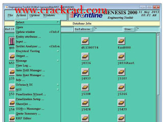 Here you can select the jobs to be restored or deleted. You can filter your
selection according to a number of different criteria:
• Genesis user name
• Customer name
•Data Repository name
• Date when job was last accessed, backed up, or created
• User-designed custom filter created with the same methods used to
create job filters in the Genesis clipboard.(See Doc. 102, Engineering
Toolkit, for more information on creating job filters.)
Once the list of jobs appears in the display area, you can select only those
jobs that require further processing.
• Select the desired jobs by clicking on the job name.
• Select multiple jobs by holding down the CTRLkey and then clicking
on the job names desired.
You may Select Alljobs that appear in the list by clicking the appropriate
button. Or you may clear the list and start over by clicking Clear All.
Creating a Backup Repository
To create a backup repository:
1. Create a folder in which you will place the configuration and setup files.
Example: C:\genesis\backup.
2. Define a new environment variable, FRONTLINE_BACKUP_DIR, and
then add the path to the backup folder in the variable definition.
3. Inside the backup folder indicated by FRONTLINE_BACKUP_DIR,
insert two new text files bakdblistand bakconfig. Update them according
to the instructions below
New Resize Algorithm
A new algorithm for the Resize operation, introduced in Version 10.0,
eliminates all unexpected behaviors that may occur during Resize
operations. It also improves Fill and Pattern Fill operations.
I/O
Support for Input of New IPC2581A Format
As of version 10, Genesis can support input in the new IPC2581A format.
This is a licensed option - it requires the inp2581license. Data input is
carried out through the standard Import Job function.
Disclaimer
This input was tested only on the sample data provided by the
IPC2581 consortium. Frontline recommends at this stage to ask
customers to send reference data (ODB++ or RS274X) to validate the
input.
Graphic Editor
Interactive Spacing Repair Editor
Introduction
The Interactive Spacing Editorenables you to define spacing
requirements between two selected features at the start of the editing
process, and provides the tools necessary to change one or both features in
order to obtain the desired spacing.
Note If the two selected features touch each other, definition of spacing
requirements cannotbe performed.
There is often a need to resolve interactively spacing problems between
board features. The features could be on the same layer (copper2copper,
clearance2clearance) or on different layers (clearance2copper,
drill2copper, rout2copper). Genesis provides a number of DFM actions to
resolve spacing difficulties, but these DFM actions cannot solve ALL
possible spacing problems, as it would be far too complicated to define
rules that would cover every possible spacing repair problem. A better
solution would be to create automaticDFM actions to solve the majority
of definable spacing problems, and use an interactive tool to repair the
more complex, or less obvious, problems.
Existing Genesis repair tools enable you to move and stretch different
features on a board, but none of these tools enables you to define the
spacing required between features as a starting point of the editing
Here you can select the jobs to be restored or deleted. You can filter your
selection according to a number of different criteria:
• Genesis user name
• Customer name
•Data Repository name
• Date when job was last accessed, backed up, or created
• User-designed custom filter created with the same methods used to
create job filters in the Genesis clipboard.(See Doc. 102, Engineering
Toolkit, for more information on creating job filters.)
Once the list of jobs appears in the display area, you can select only those
jobs that require further processing.
• Select the desired jobs by clicking on the job name.
• Select multiple jobs by holding down the CTRLkey and then clicking
on the job names desired.
You may Select Alljobs that appear in the list by clicking the appropriate
button. Or you may clear the list and start over by clicking Clear All.
Creating a Backup Repository
To create a backup repository:
1. Create a folder in which you will place the configuration and setup files.
Example: C:\genesis\backup.
2. Define a new environment variable, FRONTLINE_BACKUP_DIR, and
then add the path to the backup folder in the variable definition.
3. Inside the backup folder indicated by FRONTLINE_BACKUP_DIR,
insert two new text files bakdblistand bakconfig. Update them according
to the instructions below
New Resize Algorithm
A new algorithm for the Resize operation, introduced in Version 10.0,
eliminates all unexpected behaviors that may occur during Resize
operations. It also improves Fill and Pattern Fill operations.
I/O
Support for Input of New IPC2581A Format
As of version 10, Genesis can support input in the new IPC2581A format.
This is a licensed option - it requires the inp2581license. Data input is
carried out through the standard Import Job function.
Disclaimer
This input was tested only on the sample data provided by the
IPC2581 consortium. Frontline recommends at this stage to ask
customers to send reference data (ODB++ or RS274X) to validate the
input.
Graphic Editor
Interactive Spacing Repair Editor
Introduction
The Interactive Spacing Editorenables you to define spacing
requirements between two selected features at the start of the editing
process, and provides the tools necessary to change one or both features in
order to obtain the desired spacing.
Note If the two selected features touch each other, definition of spacing
requirements cannotbe performed.
There is often a need to resolve interactively spacing problems between
board features. The features could be on the same layer (copper2copper,
clearance2clearance) or on different layers (clearance2copper,
drill2copper, rout2copper). Genesis provides a number of DFM actions to
resolve spacing difficulties, but these DFM actions cannot solve ALL
possible spacing problems, as it would be far too complicated to define
rules that would cover every possible spacing repair problem. A better
solution would be to create automaticDFM actions to solve the majority
of definable spacing problems, and use an interactive tool to repair the
more complex, or less obvious, problems.
Existing Genesis repair tools enable you to move and stretch different
features on a board, but none of these tools enables you to define the
spacing required between features as a starting point of the editing
Predator_CNC_Editor_v10_tutorial
Predator MDC v10.0.156 improves all charts with a new Chart Zoom feature via CTRL+Left mouse and pressing the R key to return to the previous view. In addition, the Machine Timeline chart has been significantly improved. Specifically the following improvements have been made:
Improved CSV import support to import commas, double quotes and optional double quotes
Improved Machine Timeline Chart with new command filter
Improved Machine Timeline with new CTRL+Left and CTRL+Right arrow support for next and previous tooltip events
Improved Machine Timeline with better event display and tooltips
Improved My Favorites to honor additional chart options and chart permissions
Improved Event Time Analysis chart to default to drilldown style
Eliminated Trend Analysis chart combinations that are not feasible
Improved MDC APIs to have a v10 specific reference. Non script IDEs need to update to the new MDC API object reference
Improved Splash screen display for specific screen resolutions
Improved upgrade dialog to eliminate virtual network IDs
Improved English, Chinese, Spanish, Japanese, Turkish, Polish, French, German, Italian and Portuguese language resources
Improved online help with additional topics and fixed a number of help IDs
Fixed a bug with function keys and the New Event dialog
Fixed a bug when switching between multiple databases
Predator PDM Enterprise has enhanced the shopfloor dialogs with New Machine Events and Tracker style Check In and Out dialogs. In addition, the following improvements have been made:
 Added -UNRELEASED to change manufacturing and quality status workflow
Improved online help
Improved -viewvaultitem command line to support wildcards
Improved -viewvaultitemdialog command line to support wildcards
Improved machine wizards
Improved the Oracle database login screen
Improved displaying the database name and host within the statusbar
Improved check out warning message
Improved display of LF only style CNC files within the shop floor windows
Fixed a bug with editing a list item
Added -UNRELEASED to change manufacturing and quality status workflow
Improved online help
Improved -viewvaultitem command line to support wildcards
Improved -viewvaultitemdialog command line to support wildcards
Improved machine wizards
Improved the Oracle database login screen
Improved displaying the database name and host within the statusbar
Improved check out warning message
Improved display of LF only style CNC files within the shop floor windows
Fixed a bug with editing a list item
powerbench v3.4.1_tutorial
Fugro-Jason announced today the availability of PowerBench Geology for geological interpretation. This addition to the PowerBench suite was acquired from a large independent oil company that had invested more than 20 years in developing the underlying technology. PowerBench is a Windows®-based application suite for Geology, Geophysics, Petrophysics, and Engineering.
''Geological interpretation is fundamental to providing a single consistent model of the earth,'' said Eric Adams, Managing Director of Fugro-Jason. ''Through this strategic acquisition we were able to add time-tested capability to PowerBench and make that capability available to our customers very rapidly.''
 PowerBench Geology enables unified handling of subsurface geology, well bore equipment and production data. It features an integrated base map and interpretation canvas that handles tens of thousands of wells quickly and efficiently, and a geologic cross section builder that features structural and stratigraphic cross section interpretation. The PowerBench suite encompasses the E&P workflow and includes petrophysical interpretation, seismic and rock property volume interpretation, geologic interpretation, mapping, framework and 3D property modeling, and streamline simulation.
 PowerBench Geology enables unified handling of subsurface geology, well bore equipment and production data. It features an integrated base map and interpretation canvas that handles tens of thousands of wells quickly and efficiently, and a geologic cross section builder that features structural and stratigraphic cross section interpretation. The PowerBench suite encompasses the E&P workflow and includes petrophysical interpretation, seismic and rock property volume interpretation, geologic interpretation, mapping, framework and 3D property modeling, and streamline simulation.
Mastercam_x7_v16.05_crack_tutorial
Mastercam X7 also includes Mastercam Mill-Turn, designed to simplify programming for complex Mill-Turn machines.
IMPORTANT If you are interested in purchasing this product, please contact your local Mastercam reseller.
The centerpiece of Mill-Turn is the Code Expert application. Like the new Tool Manager, the Code Expert runs in the new Extensions window. Code Expert incorporates an entire suite of tools for managing multitasking applications.
Mastercam is known for powerful NC programming. But it also delivers a suite of shop-tested design tools including 3D surfacing and solids.
Click on the above tabs for a quick overview of CAD choices. Or choose from the buttons on the right for more detailed information.
What does this mean for you? It means that when you choose Mastercam, you’re using innovative CAM software that has helped more shops achieve success than any other. It also means that skilled Mastercam users are much easier to find.
Mastercam’s Support is Second to None
Mastercam is supported by a worldwide network of dedicated, expert resellers who focus exclusively on ensuring that Mastercam fits your needs. They know the software, know your area, and are there when you need them.
 Mastercam also enjoys a large online user community that offers advice, help, tips and tricks to fellow Mastercam programmers.
Mastercam is Dedicated to the Future
As one of the pioneers in PC-based CAD/CAM, Mastercam has a long history of company security and health. As a privately-owned company, we continue to focus exclusively on the needs of NC programmers. And as a CAD/CAM innovator, we’ll be here to work with you as you move into the future.
Mastercam also enjoys a large online user community that offers advice, help, tips and tricks to fellow Mastercam programmers.
Mastercam is Dedicated to the Future
As one of the pioneers in PC-based CAD/CAM, Mastercam has a long history of company security and health. As a privately-owned company, we continue to focus exclusively on the needs of NC programmers. And as a CAD/CAM innovator, we’ll be here to work with you as you move into the future.
SDS/2-v7.313-Design-Data-download-crack
SDS/2 Detailing offers the highest level of automation and intelligence available in 3D steel detailing.
As the detailer inputs members, like columns and beams, connections are automatically designed with their necessary materials, bolts, holes and welds. SDS/2 Detailing takes a uniquely intelligent approach in its connection design by considering framing conditions and erectibility, automatically performing clash prevention as a part of its connection design. In addition, SDS/2 Detailing can value engineer the connections on a project, helping users to design the most economical connections to fabricate and erect. No other 3D detailing product can do this automatically.
SDS/2’s expanded design calculations give users the full formulas for all force checks of connections. With SDS/2, users can see how the software arrives at the connection results, and assists engineers in reviewing
 SDS/2 Approval supports AISC's methodology for model approval by allowing communications like sketches, addendums and RFIs, as well as status updates, to be stored and exchanged via the 3D model. Whether you choose to approve models on a project using the Hybrid method of the Full Model Approval method, there is an SDS/2 solution that supports either approach.
The free SDS/2 Viewer allows the model to be used as a supplemental tool to more easily verify drawings. From the model, engineers can view information during the approval process, like connection design calculations, material information, member status and more.
Using SDS/2 Approval, engineers can receive submittals via the model, and then use it to approve, reject or note changes to be made. They can then transmit that information back to the detailer or fabricator's model via tools provided by SDS/2 Approval.
SDS/2 Approval supports AISC's methodology for model approval by allowing communications like sketches, addendums and RFIs, as well as status updates, to be stored and exchanged via the 3D model. Whether you choose to approve models on a project using the Hybrid method of the Full Model Approval method, there is an SDS/2 solution that supports either approach.
The free SDS/2 Viewer allows the model to be used as a supplemental tool to more easily verify drawings. From the model, engineers can view information during the approval process, like connection design calculations, material information, member status and more.
Using SDS/2 Approval, engineers can receive submittals via the model, and then use it to approve, reject or note changes to be made. They can then transmit that information back to the detailer or fabricator's model via tools provided by SDS/2 Approval.
Subscribe to:
Posts (Atom)
