2015-01-22

Downstream_CAM350_V11_ blueprint_v4.0_CRACK_tutorial

CAM350 for PCB Designers and Electrical Engineers
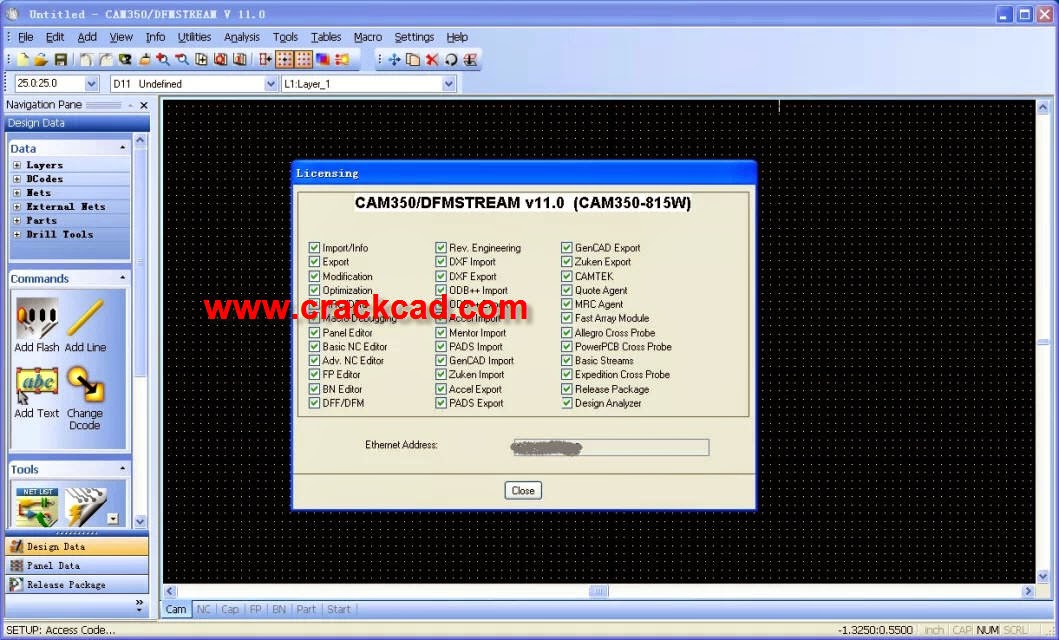
CAM350 will import your CAD database or you can choose to import Gerber files. It will then verify that the electrical characteristics match the design intent. Errors can occur in translation such as accidental inclusion of non electrical items in Gerber output or problems with manual separation of voltages on a plane layer. CAM350 will graphically match up original design files with Gerbers to ensure accuracy by locating any disparities.

CAM350 also offers Design Rule Checks (DRC) to verify the Gerber layers match the design rules in your CAD system and the capabilities of your fabricator as well. CAM350's Design for Fabrication (DFF) tools insure the board not only matches manufacturing capabilities, but also searches out design flaws that may affect yields resulting in missed deliveries and delayed product release.

CAM350’s Design for Fabrication (DFF) Analysis pulls fabrication rules into the PCB design domain and presents them in a way that is understood by the PCB designer. DFF Analysis verifies the PCB database to find issues that may cause problems when entering into the fabrication process.

Directly import your design data for true WYSIWYG representation
Analyze, identify, and fix manufacturing flaws that may cause delay
Inspect for etching, soldermask, thermal, and spacing violations
Verify and maintain design integrity and intent
Easy to learn, use and implement


CAM350 for CAM Engineers
CAM350 automates the PCB CAM engineering department by preparing and optimizing the design files for fabrication. Getting designs quickly through fabrication is a very complex process and effectively managing each operation is the key to moving into high-volume production. With a solution for every operation, CAM350 manages data input and preparation, through analysis, test, mill and drill to final bare-board production.

Any complication during fabrication will make the job time consuming and labor intensive, decreasing profitability. CAM350 can safeguard against these setbacks.

When using CAM350, the CAM engineer will accurately prepare, optimize and process the design data. CAM350 will perform an in depth analysis of the data to locate manufacturing violations, it will create optimized mill and drill files, prepare test data, and produce panelization strategies, all resulting in an automated, highly effective process.

Seek out and repair manufacturability flaws in the design
Create NC files quickly and accurately
Optimize the drill and mill machine performance
Streamline tooling with panelization functionality
Extract the essential data to drive test equipment
Optimize test machine performance and probing time
Identify collisions, break-outs, and un-probable conditions
2015-01-21

MVTec_HALCON_12_download_tutorials_crack

Matching, Measuring, 3D Vision, Morphology, Blob Analysis
Calibration, OCR & OCV, Bar Code & Data Code Reading, and more
Easy Programming in C, C++, and .NET languages like C# or VB.NET
Integrated Development Environment HDevelop
Support of Multi-Processor/-Core Comput
Highlights

The solution for the full range of applications in the field of machine vision and board, wafer & die inspection, medical image analysis, automotive and robotics, surveillance, and remote sensing
Large library of more than 2000 operators for low, medium, and high level image processing
Integrated development environment (IDE) for machine vision: HDevelop
Easy programming in C, C++, C#, Visual Basic .NET, and Delphi
Usage: product development, research, and education
Available for 32/64-bit Windows Vista / 2008 / 7 / 2012 / 8, 64-bit Linux, OS X 10.8 / 10.9 / 10.10
Support of multi-core and multiprocessor computers
High performance by using SSE2 and AVX, as well as automatic GPU acceleration
Support of hundreds of industrial cameras and frame grabbers, also for standards like GenICam, GigE Vision, IIDC 1394, USB, USB3 Vision, and Camera Link

Features

Revolutionary methods for 3D vision
Matching to find even rotated or partly occluded objects
Blob analysis with more than 50 shape and gray value features
High-accuracy measuring
Optical character recognition and verification (OCR/OCV)
Arbitrarily shaped regions of interest (ROIs) for significant flexibility and speed
Detection of lines, circles, and ellipses with an accuracy of up to 1/50 pixel
Extremely fast morphology
Color image processing
Processing of extremely large images (more than 32k x 32k) without a limit
Image sequence processing (e.g., for surveillance tasks)
Accurate 3D camera calibration
And much more ...

2015-01-20

LightTools_v8.2_download_tutorial

LightTools Features

LightTools delivers true design capabilities, accurate analyses, and high-powered product visualization features that will help you get illumination systems to market faster. Explore LightTools’ key features in more detail to find out how it can meet your specific illumination design needs.

Rapid Model Creation with LightTools

LightTools’ robust design features help you quickly and efficiently create and modify your illumination system design, from initial concept phases to subsequent engineering iterations and refinements.
Key design features
  • Sophisticated solid modeling with full optical accuracy
  • State-of-the-art ray tracing speed, with full user control of accuracy and resolution requirements
  • Create a light source from any geometric model, for unlimited flexibility to create custom sources
  • Application-specific utilities to help you quickly build a complete model
  • Extensive source and materials libraries, including LEDs and BSDF measurements
  • Robust data exchange support for mechanical CAD data
  • Interactive, dynamic link with SolidWorks®
  • Multiple immersion for modeling the embedded phosphor in an encapsulated LED
  • Fully optimizable skinned solids for creating efficient LED couplers, solar concentrators, and other complex optical surfaces
  • User-defined materials to model phosphor-based white LEDs
  • Textures – 2D, 3D, and user defined – with flexibility to vary the shape, size, and spacing of texture elements
  • Calculate the color rendering index (CRI) on any receiver – ideal for LED and luminaire design
  • Intensity data collection that enables data exchange with other lighting design software through the IES and LDT data formats
  • Point-and-shoot ray tracing for real-time, immediate feedback on your system’s light behavior during design iterations


Reach the Best Design Solution Faster with LightTools Optimization

LightTools is the first illumination design and analysis software to deliver a fully integrated system optimization tool. The LightTools optimization module improves the performance of virtually any type of illumination system, and gives designers tremendous flexibility to choose from hundreds of system parameters to designate as variables in order to achieve specified luminance, illuminance or output intensity distribution goals.
Key optimization features
  • Full integration with LightTools 3D solid modeling ensures that the optimizer delivers practical, realistic solutions that yield the best possible system performance, in a fraction of the time it would take to accomplish manually
  • Augmenting the capabilities of the LightTools optimizer is the parametric controls feature. Used in conjunction with the optimizer or in earlier stages of system design, this feature improves parameter management efficiency; by enabling the properties of various system elements to be associated, parametric controls permit global changes on a model to be accomplished by varying a single parameter.
  • Backlight Pattern Optimization for automatic design of backlight extraction patterns for LCDs, cell phone key pads, and automotive instrument clusters
  • Parameter Sensitivity analysis for selecting the best set of variables prior to system optimization
  • Support for optimization of optical elements, parts, and assemblies dynamically linked from SolidWorks®

Worknc_v23_tutorials_crack

WorkNC CAM software is the premier automatic CNC software for surface or solid models in mold, die and tooling businesses for 2 to 5-axis CNC programming. WorkNC is used by all western, Japanese and Korean automotive makers and well-known OEMs from a range of other industries.
WorkNC is best of breed, complementary CAM software that enhances all design and manufacturing systems by providing the most reliable, efficient, easy-to-program cutter paths, resulting in unmatched productivity and safety.
WorkNC 5-Axis Machining
WorkNC brings the benefits of 5-Axis machining to all users by taking the complexity out of 5-Axis machining. WorkNC 5-Axis includes powerful, easy-to-use programming and integrated collision avoidance.
With WorkNC, 5-Axis programming is easy, safe and reliable allowing you to automatically generate 5-Axis toolpaths for the majority of your jobs. 

Features at a glance

  • Efficient toolpath generation
  • Easy toolpath preparation based on guide curveset, sections or surfaces.
  • Auto 5: Automatic conversion of 3-Axis toolpaths to 5-Axis
  • Specialized strategies for individual applications such as trimming, pocketing, blade and tube machining, impellers and laser cutting
  • Complete simulation.

WorkNC Auto 5

WorkNC Auto 5 is a truly unique and revolutionary innovation in the field of 5-Axis machining. Users can now automatically generate 5-Axis toolpaths based on existing 3-Axis toolpaths while taking into account the specific kinematics of the 5-Axis milling center selected.
WorkNC Auto 5 automatically generates collision free 5-Axis toolpaths from existing 3-Axis toolpaths. It enables the use of short, rigid cutters and allows more of the job to be finished in one setting, reducing the number of electrode burning operations required to finish a component.

2015-01-06

Lumerical_FDTD_Solutions 8.11 _tutorial_download

FDTD Solutions is a 3D Maxwell solver, capable of analyzing the interaction of UV, visible, and IR radiation with complicated structures employing wavelength scale features.
FDTD Solutions empowers designers to confront the most challenging photonic design problems. Rapid prototyping and highly-accurate simulations reduce reliance upon costly experimental prototypes, leading to a quicker assessment of design concepts and reduced product development costs. FDTD Solutions can facilitate your success in diverse application areas, from fundamental photonics research to current industrial applications in imaging, lighting, biophotonics, photovoltaics, and many more.
  • Highly-optimized computational engine able to exploit multi-core computing systems in everything from laptops to high-performance computing clusters.
  • Broad operating system and hardware support (including Amazon EC2) enables for high throughput design assessment on all available leading-edge computational systems.
  • Parallelized parameter sweep/optimization framework combined with concurrent computing on multiple computers allows for rapid virtual prototyping.
  • Proprietary multi-coefficient material modeling capability combined with Lumerical’s flexible material framework accurately accounts for broadband linear material dispersion as well as nonlinear, gain and anisotropic effects.