2012-09-27
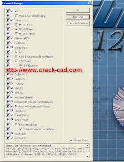
GibbsCAM_2012_v10.3.7_download
GibbsCAM 2012 Production Milling supports 2-axis through simple 3-axis wireframe machining with full functionality for contouring, pocketing with unlimited bosses/islands, thread milling, face milling, 2D/3D spiral creation, drilling with support for many drill cycles, tapping, and boring. Simple 4th-axis positioning is also supported. Automatic cycles for face milling, such as spiral, zig-zag, back and forth and one direction, allow material to be cleaned off the top of a part. GibbsCAM Production Milling provides easy-to-use, powerful programming capability for your machine tools.
Gibbs and Associates, developer of GibbsCAM 2012 software for programming CNC machine tools and a Cimatron (NASDAQ: CIMT) company, today announced its leadership role in supporting phase one of the DMG/Mori Seiki standardization initiative. It will ultimately provide DMG/Mori Seiki customers a smooth and reliable flow of programming data from any CAM system to DMG/Mori Seiki machine controls. This will enable the full use of the features of their machines and controls without the need for custom post-processors or machine simulation models. The technology is based upon DMG/Mori Seiki’s implementation of the standard APT (automatically programmed tool) language, with DMG/Mori Seiki extensions that are supported within GibbsCAM. DMG/Mori Seiki’s initial focus during phase one is on its 3- to 5-axis machining centers and controls, with an ultimate goal of enabling the technology for all of its machines, including the most challenging multi-task machines. As new machines and machine functions are introduced, DMG/Mori Seiki and Gibbs will incorporate the new capabilities into their APT implementation.
GibbsCAM to Support Multiple Machine Tool Builders at IMTS
Parts to be Programmed with GibbsCAM 2012+ and Live Personal Demonstrations
Moorpark, CA - August 27, 2012
Gibbs and Associates, developer of GibbsCAM® software for programming CNC machine tools and a Cimatron (NASDAQ: CIMT) company, today announced that it will support various machine tool companies with its GibbsCAM 2012+ NC programming software at the International Machine Technology Show (IMTS 2012), September 10-15, 2012, at McCormick Place, Chicago. Some machine tool builders will be machining parts programmed with GibbsCAM, while others will also host GibbsCAM demonstrations, highlighting the software’s latest capabilities and its leadership in programming high-speed machining and multi-task and multi-axis machines. GibbsCAM 2012+ includes new features and enhancements across the product line, with a continued emphasis on ease of use, so that customers can achieve the highest speed, accuracy, efficiency and reliability in programming. In addition to supporting machine tool partners, GibbsCAM will have its own exhibit in Booth E-3310.
Autoform_plus_r4_download
AutoForm plus r4-Incrementalplus
Rapid and Accurate Simulation and Validation of the Complete Stamping Process
AutoForm-ThermoSolver
AutoForm-ThermoSolver
Efficient Simulation of Hot Forming and Quenching Processes
AutoForm-DieDesigner
AutoForm-DieDesigner
3D-Die-Layout and Process Optimization
AutoForm-Sigma
AutoForm-Sigma
Sensitivity Analysis, Optimization and Robustness
AutoForm-Compensator
AutoForm-Compensator
Geometry Compensation of Part and Tool Based on Springback Results
AutoForm-Trim
AutoForm-Trim
Automatic Determination of Optimum Trim Line and Blank Outline
AutoForm-ProcessPlanner
AutoForm-ProcessPlanner
Effective Process Planning
AutoForm-CostCalculator
AutoForm-CostCalculator
Rapid Production Sequence Definition with Sophisticated Tool Cost Calculation
AutoForm-BlankDesigner
AutoForm-BlankDesigner
Rapid Design of Cost-Optimized Blanks
AutoForm-Nest
AutoForm-Nest
Cost-Optimized Nesting of Blanks
AutoForm-OneStep
AutoForm-OneStep
Engineering Manufacturable Sheet Metal Parts
AutoForm-PartDesigner
AutoForm-PartDesigner
Easy and Rapid Part Modifications
AutoForm-DieAdviser
AutoForm-DieAdviser
Optimal Wear Protection
AutoForm Hydroforming
AutoForm Hydroforming
Rapid Analysis and Simulation of Entire Hydroforming Design Chain
AutoForm-DataManager
AutoForm-DataManager
Efficient Management of AutoForm Data
AutoForm-ReportManager
AutoForm-ReportManager
Creating Presentation Reports of AutoForm Results
AutoForm-HemPlanner
AutoForm-HemPlanner
Efficient Planning of Hemming Processes
AutoForm-ProcessDesigner^forCATIA
AutoForm-ProcessDesignerforCATIA
Rapid Creation of CAD Quality Die Faces
AutoForm-OneStep^forCATIA
AutoForm-OneStepforCATIA
OneStep Feasibility Assessment inside CATIA
AutoForm-CATIA5
AutoForm-CATIA5
Direct Integration of AutoForm Software in CATIA V5
AutoForm-NX
AutoForm plus r4 p-NX
Direct Integration of AutoForm Software in NX
EasyBlank Inventor
EasyBlank Inventor
Analysis of Stamped Parts Embedded within Autodesk® Inventor® Software
EasyBlank
EasyBlank
MatForm
MatForm
AutoForm-Sigma®
Software for Sensitivity Analysis, Optimization and Robustness
The AutoForm-Sigma software module is specialized for analyzing and improving the robustness of sheet metal products and processes. It serves to improve and validate the forming process, and to reduce or eliminate part rejects.
With AutoForm-Sigma, products and processes can be designed so that the resulting manufacturing process is most efficient and stable while meeting desired quality targets. The influence and sensitivity of design parameters are easily analyzed which leads to improved process know-how and shorter development times. In addition, statistical process control techniques can already be applied in the design phase, taking into account the noise and variability that are inherent in the forming process. Therefore, sheet metal formers can address and solve key manufacturing problems much before going into production, with obvious advantages.
AutoForm-Sigma provides the following benefits:
Shorter development and tryout times -
because the forming process becomes more transparent and process know-how is improved
More stable manufacturing processes during the entire production cycle -
through identification of the process window
Less plant downtime, fewer tool adjustments and fewer part defects -
because of more robust manufacturing processes
More robust manufacturing processes -
through quality and process capability analyses
AutoForm-Sigma is fully integrated into the AutoForm work environment. Unique on the market, it automatically analyzes and displays the results (e.g. influence, sensitivity, process capability Cpk) directly on the parts – no time consuming investigations of abstract numbers and diagrams are needed any more. No other software offers this new methodology which can be used by die face designers and engineers, without requiring years of specialized expertise.
AutoForm-Sigma’s main features include:
Easy definition of design parameters
Automatic start of multiple simulations
Statistical techniques pre-defined and ready for user application
Identification of dominant design parameters
Determination of influence and sensitivity of design parameters
Automated process optimization
Determination of noise and variability of process parameters
Integration of Statistical Process Control (SPC) and simulation
Identification of process window
2012-09-11
Moldex3D-R11-download
Moldex3D is a suite of professional CAE tools that enable more accurate and more efficient plastic part verification and mold optimization. It helps global designers create better products to meet market demands. It also helps manufacturers produce high-quality plastic parts at lower cost. Moldex3D leads users to overcome severe industrial challenges and strengthen core competitiveness.
Moldex3D R11.0 brings several breakthroughs on solver enhancement and user friendliness. It now provides the most complete industrial processing simulations, including advanced hot runner optimization, co-injection molding, microcellular molding, underfill encapsulation, etc. It also continues improving pre-processing and post-processing functionalities that help users acquire optimal solutions more easily and more efficiently.
Moldex3D R11.0 builds its outstanding capabilities on past releases and adds innovation for better performance and user experience, offering the following new features and benefits:
Advanced Support for Pre-Processor
Accuracy Improvements for Simulations
Enhanced Efficiency for Simulations
New Simulation Capabilities
Material Database Updates
High Performance Computing
Advanced Support for Pre-Processor
Moldex3D R11.0 has improved its exclusive pre-processors, Moldex3D Mesh and Designer, to help users avoid most difficulties in the pre-processing preparation.
Quality Improvements in Moldex3D Mesh
Moldex3D Mesh highly improves the quality of solid mesh and surface mesh. Aimed to circular features, the meshing processor will assign at least six node seeds automatically in a circular region, which means a better node density distribution to describe a circular feature. It will avoid common geometric distortion in circular surface mesh and bring more accurate simulations.
A specific geometric feature can be perfectly portrayed
An enhanced function has also been added for users to find a region with small edge length on one mesh edge. Users can setup ideal minimum edge length to identify disqualified surface elements for further improvements. It will help users enhance mesh quality.
Features and Enhancements in Designer
Moldex3D Designer develops several new features:
Enables users to directly modify local geometric thickness on a 3D model. It is more efficient for users to run simulations for thickness changes.
Provides a user-friendly tool to draw an arc curve and attribute it as a runner or a cooling channel. It allows users to design feeding or cooling systems depending on individual needs.
Supports to import 3D models of cooling channels in STL format directly from CAD software. Users can build up complex cooling systems more easily.
Users can create a complex cooling system in STL
Enhances the meshing performance especially for models with large runner volume. Its function of auto grid distribution will automatically distribute more elements in cavities than that in runner. It will lead to an increase on mesh and result resolutions in critical regions.
Supports to specify symmetric settings of models
JMAG-Designer-v11.1-download
JMAG-Designer is a simulation software for electromechanical design striving to be easy to use while providing versatility to support users from conceptual design to comprehensive analyses
Electrical Machine Design
(IPM, SPM, SR, Spindle, Induction, Stepper Motor, Alternator...)
Basic Characterstics Analysis
(N-T Analysis, Torque Ripple Analysis)
Inductance Calculation,
Efficiency Analysis
Magnetization, Demagnetization, Eccentricity Analysis
Loss Analysis
(Iron Loss, Eddy Current Analysis)
Thermal Analysis
Structural Analysis
(Stress, Centrifugal Force, Sound Pressure Analysis)
Transformer / Reactor Design
Basic Characteristics Analysis
Structural Analysis
(Sound Pressure)
Loss Analysis
Thermal Analysis
Busbar Design
Current Distribution
Inductance Claculation
Thermal Analysis
Structural Analysis
Induction Heating Analysis
(Printer Roller, Inductance Frunace, Gear,
Cooking Heater, Drive Shaft, Crankshaft...)
Eddy Current Density
Distribution
Joule Loss Density Distribution
Temperature Distribution
and Variation
Vero_ViSi_ 20.0_cracked
VISI v20 q2 is acknowledged as one of the world's leading PC based CAD / CAM solutions for the Mould & Die industries. It offers a unique combination of applications, fully integrated wireframe, surface and solid modelling, comprehensive 2D, 3D and 5 axis machining strategies with dedicated high speed routines. Industry specific applications for plastic injection tool design including material flow analysis and progressive die design with step-by-step unfolding provide the toolmaker with unsurpassed levels of productivity.
Vero Software offers dedicated solutions that eliminate the links between varying software suppliers and the solid-to-surface or CAD / CAM geometry conversions required by traditional systems.
VISI Modelling
Advanced CADCAM Software Solutions For The Manufacturing Industry
VISI Modelling is the foundation of all VISI products and provides a robust and powerful solid and surface modelling system based around the industry standard Parasolid® kernel. Combined with Vero’s surface technology, model analysis and 2D design, VISI Modelling offers complete flexibility to construct, edit or repair the most complex 3D data.
Features at a glance:
Easy to learn intuitive interface
Extensive CAD interfaces
Industry standard Parasolid® kernel
Combined wireframe, solid & surface modelling
Solid & surface boolean operations
Surface repair & analysis
Edge tolerance manipulation
Powerful blending
Intelligent model deformation
Fast rendering & texture mapping
Mechanical curve construction
Associative tool detailing
Automatic B.O.M. creation
Extensive range of CAD interfaces. VISI can work directly with Parasolid, IGES, CATIA v4 & v5, Pro-E, UG, STEP, Solid Works, Solid Edge, ACIS, DXF, DWG, STL and VDA files. The extensive range of translators ensures that users can work with data from almost any supplier. The ability to skip corrupt records during the import process provides a platform from where the most inconsistent data can be managed. Very large files can be handled with ease and companies working with complex designs will benefit from the ease with which their customer’s CAD data can be manipulated.
True hybrid modelling. VISI provides a dynamic structure from where it is possible to work with either solid, surface, wireframe or a combination of all three without any restrictions. Solid modelling has become a fundamental cornerstone of design but is often limited to prismatic or basic geometry. Solid modelling commands include boolean technology such as unite, subtract, extrude, revolve, sweep, cavity, intersect and hollow. Surfacing technology however provides a different set to tools and techniques for more organic, free-form geometry creation. Surface modelling functions include ruled, lofted, drive, sweep, n-sided patch, drape, tangent, draft, revolved and piped surfaces. These modelling commands combined with advanced surface editing make it easy to heal imported geometry or construct the most complex 3D data.
Surface repair and editing. Small gaps between surfaces on imported models can be automatically healed preventing the time consuming process of rebuilding very small surface patches. Where surfaces are corrupt or missing VISI will automatically create the edge curve geometry making it easy to rebuild new faces using the comprehensive surfacing suite. To ensure the new surfaces are within tolerance, the new and the old surfaces can be compared to check for min/max distance and curvature deviation. Closing a surface model to produce a solid body eliminates construction problems later in the design process and immediately brings the benefits of solid modelling to the user. The ability to seamlessly switch between solid and surface technology provides unlimited freedom, ensuring the user can work with difficult CAD data.
Subscribe to:
Posts (Atom)


