2014-12-31

2014 New software for download,tutorials,training

[Other CAD/CAM] Mastercam X8 HotFix 3_ v17.0.17986.0_Win64
[DELCAM] Delcam PowerInspect 2014 SP1
[petroleum] kingdom suite 2015
 [UGS] Siemens.NX.v10.0 Engineering DataBases
 [Other CFD] Siemens LMS Virtual Lab Rev13.1
 [Other EDA] CST Studio Suite 2014 SP6 Updat
 [PTC] PTC Creo 3.0 M020
 [Structural Analysis] DIGICORP Ingegneria Civil Design v10.0 for Autodesk AutoCAD 2015
 [Structural Analysis] ADAPT.PT.RC.2014.2
 [petroleum] Zeataline.PipeData.Pro.v9.3.2
 [SolidWorks] nPower.PowerSurfacing.v2.00.9465.for.SolidWorks2015
 [UGS] SIEMENS NX v10.0.0 Mold Wizard EasyFill Advanced
 [Structural Analysis] CSI Etabs 2013 v13.2.2
 [petroleum] Petrel 2014_DomainVideos_v1.5
 [petroleum] WinSim Design II V14
 [Other CAD/CAM] GibbsCAM_2014_10.7.19.0
 [Other EDA] Antenna Magus Pro 5.2
[Other EDA] Altera Quartus II version 14.1
 [Roads_Bridges] Adapt Builder v2012.3
[Geological Prospecting ] Blue Marble Geographic Calculator 2015
 [UGS] SIEMENS PLM NX 10 FOR WIN/LINUX
 [Structural Analysis] MechaTools.ShapeDesigner.2013
 [petroleum] schlumberger forgas v10.5.5
 [Geographic Information] Schlumberger Eclipse 2014
 [Other EDA] Frontline Genesis 2000 v10.01B2
[PTC] PTC_Creo_2.0_M130
 [SolidWorks] DS.SolidWorks.Enterprise.PDM.2015.SP1.1
 [Geographic Information] SPT Drillbench Suit 6.2
[Other CAD/CAM] VERO AlphaCAM 2015 R1
 [AGILENT] Agilent.Electromagnetic.Professional(EMPro).2015.0
 [Geographic Information] ET SpatialTechniques Products v11.2 for ArcGIS
 [MENTOR] Mentor Graphics Expedition Enterprise Flow(EE) VX.1
 [Other CAD/CAM] MicroSurvey.CAD.2015.v15.0.3.1574
 [Other CFD] CEI.Ensight.10.1.2b.GOLD.WINDOWS.MAC.LINUX
 [DELCAM] Delcam_Crispin_ShoeMaker_2015_R1_SP1
 [Dassault CATIA ] DS_CATIA_Composer_V6R2015
 [AGILENT] Agilent Advanced Design System ADS 2015.1
 [SolidWorks] SolidWorks 2015 With SP1.0
[SolidWorks] SolidCAM 2014 SP3 HF2
 [Other CAD/CAM] VERO EDGECAM V2015 R1
[Other CAD/CAM] InventorCAM 2015
[Other CFD] CAE Linux 2013 Win64
 [petroleum] Schlumberger.Hydro.GeoAnalyst.2014.2
 [petroleum] Schlumberger.AquiferTest.Pro.2014.1
[petroleum] Schlumberger AquaChem 2014.2
 [MENTOR] Mentor.Graphics.QuestaSim.v10.2c
 [Other EDA] Xilinx.Vivado.Design.Suite.2014.4
[AGILENT] Agilent.89600.Vector.Signal.Analyzer.v18
 [petroleum] Intrepid.Geophysics.GeoModeller.2014.v3.2.0
 [petroleum] Intergraph CADWorx 2015
[Management] Palisade @RISK v6.3.1
[Dassault CATIA ] Theorem.Solutions.CADverter.17.3.CATIAV5
 [Other CFD] CFTurbo_9.2.8
 [Mould Processing] AutoForm Plus R5.2.3 HotFix
| [Other CFD] XYZ TRUEGRID V3.10
 [Biomedicine] Schrodinger Suite 2014
 [BENTLEY] Bentley ProStructures V8i (SELECTseries 7) 08.11.11.297
 [Development ] Intel.Parallel.Studio.XE.2015.Update.1
 [Other EDA] Polar Instruments si900e 2013 v13.2
 [Other EDA] Mician mWave Wizard V7.10
[Geographic Information] Schlumberger Techlog 2014
 [Other EDA] SIMetrix pro 7.1
 [Other EDA] Sonnet Suite Pro v15.52
 [Water Conservancy] Aquaveo Watershed Modeling System(WMS) v9.1.12.0
 [petroleum] Invensys.SimSci-Esscor.DYNSIM.V5.2.1
 [Other EDA] Polar_Instruments_Speedstack_2013
 [Other EDA] Tanner Tools v16.12
 [Animation] Quixel.Suite.v1.8.x64
 [Dassault CATIA ] CATIA_V5-6R2014_SP4_Update
 [Development ] Indusoft.Web.Studio.v7.1.SP3.Multilingual
 [Other CFD] Dassault Systemes Simulia Abaqus v6.13.SP4
 [Other CAD/CAM] CYPE CypeCAD 2014h
 [SolidWorks] SolidCAM 2015 for SolidWorks 2012-2015
 [Other CFD] AVL.Workspace.Suite.v2014.Linux.win
[Other EDA] Nuhertz_Filter_Solutions_2014
 [Other CAD/CAM] InventorCAM 2014
 [Other EDA] Infolytica MotorSolve 4.1.1
[Other CAD/CAM] SolidCAM2014_SP3_HF1
 [Other EDA] NI.LabVIEW.2014.V14.01
[Other EDA] CST Studio Suite 2014 with SP5
[BENTLEY] Bentley OpenPlant Modeler V8i SS5 08.11.09.440
 [BENTLEY] Bentley ProjectWise V8i SS4 08.11.11.590
 [Math Statistics] Trimble Business Center HCE 3.20
 [Other EDA] FABmaster v8G2
 [Other EDA] Mathworks Matlab R2014b for linux
[Mould Processing] Stampack v6.1.1
 [Other EDA] Etap PowerStation v12.6
 [Math Statistics] Trimble Business Center v3.4
 [SolidWorks] Logopress3.2015.SP0.2
 [Geographic Information] Pitney.Bowes.MapInfo.Pro.v12.5.1.122
 [Other CAD/CAM] SolidThinking Design 2014 build 3966
[Control] Automation Studio 6.0
 [Other CFD] PumpLinx V3.4.3
 [Other CAD/CAM] HiCAD 2014 Service Pack 2
[BENTLEY] Bentley Map Enterprise V8i SS4 08.11.09.503
 [PTC] PTC Creo Elements Pro 5.0 M250
 [Optics] Lumerical_FDTD_Solutions 8.11
 [Optics] lumerical_MODE_Solutions_7.5.318
 [Other EDA] Altium Designer 15.0.7 Build 36915
 [Other EDA] CAM350 V11 with blueprint v4.0

  • Contact:crackcad@gmail.com

2014-12-16

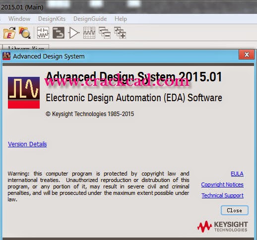
Agilent-Advanced-Design-System-ADS-2015-Crack

Advanced Design System (ADS)
Advanced Design System is the world’s leading electronic design automation software for RF, microwave, and high speed digital applications. In a powerful and easy-to-use interface, ADS pioneers the most innovative and commercially successful technologies, such as X-parameters* and 3D EM simulators, used by leading companies in the wireless communication & networking and aerospace & defense industries. For WiMAX™, LTE, multi-gigabit per second data links, radar, & satellite applications, ADS provides full, standards-based design and verification with Wireless Libraries and circuit-system-EM co-simulation in an integrated platform. Watch our ADS 30-Second Demos to see the powerful and easy-to-use ADS interface in action.

Key Benefits of ADS

Complete, integrated set of fast, accurate and easy-to-use system, circuit & EM simulators enable first-pass design success in a complete desktop flow
Application-specific DesignGuides encapsulate years of expertise in an easy-to-use interface
ADS is supported exclusively or months earlier than others by leading industry and foundry partners
Advanced Design System (ADS) continues to lead the RF EDA industry with the most innovative and commercially successful technologies, including Harmonic Balance, Circuit Envelope, Transient Convolution, Keysight Ptolemy, X-parameter*, Momentum and 3D EM simulators (including both FEM and FDTD solvers). With ADS’s Wireless Libraries and circuit-system-EM co-simulation technology, ADS provides full, standards-based design and verification within a single, integrated platform.

Download the ADS Key Features PDFKey Features
Complete schematic capture and layout environment
Innovative and industry leading circuit and system simulators
Direct, native access to 3D planar and full 3D EM field solvers
Largest number of process design kits (PDKs) developed and maintained by leading foundry and industry partners
EDA and Design Flow Integration with companies such as Cadence, Mentor, and Zuken
Optimization Cockpit for real-time feedback and control when using any of 12 powerful optimizers
X-parameter model generation from circuit schematic and Keysight's NVNA for nonlinear high-frequency design
Up-to-date Wireless Libraries enable design and verification of the latest emerging wireless standards
  • Please contact:crackcad@gmail.com

2014-12-10

Lumerical_MODE_Solutions_Ver.7.5_tutorial_download

Comprehensive waveguide design environment for the analysis and optimization of planar integrated optical waveguides, components and fibers

MODE Solutions’ variational FDTD (varFDTD) solver can efficiently simulate the propagation of optical fields in time without making any assumptions about an optical axis or the materials used. The built-in frequency domain monitors automatically perform the necessary calculations to return the continuous-wave results.
This propagation capability is based on an FDTD technique customized for omni-directional propagation within waveguide components. This method employs a highly optimized computational engine, as well as advanced meshing routines.  The combination of this propagation capability and the eigenmode solver technology provides engineers with the ideal environment for virtual prototyping of large-scale high index contrast waveguide components, reducing the need for expensive, time-consuming manufactured prototypes.

Eigenmode expansion (EME) solver

Figure 2:(Right) The transmission as a function of taper length for the spot-size converter in [1] (also pictured on the left side) calculated using the EME solver and 3D FDTD. The EME simulation takes about 1 minute to simulate 101 different taper lengths (blue squares), whereas the same device simulated in 3D FDTD takes about 6 hours for 11 different taper lengths (green squares).

The EME method is a fully vectorial and bi-directional technique to solve Maxwell's equations. The methodology relies on the modal decomposition of electromagnetic fields into a basis set of eigenmodes, which are computed by dividing the geometry into multiple cells and then solving for the modes at the center of each cell.  Scattering matrices for each cell are formulated by applying boundary conditions at the interface between each cell. The solution to each cell is then propagated bi-directionally to calculate the total transmission and reflection of the device, as well as the final field profile. The EME method has several advantages over other propagation methods:
  • Beam propagation methods (BPM): unlike BPM, which relies on a slowly varying envelope approximation, the EME method makes no such approximations and is a rigorous technique. The accuracy of BPM also becomes compromised for propagation at large angles, or in components with high refractive-index contrast, making it unsuitable for photonic components manufactured from silicon or other high index contrast material systems.
  • Finite-difference time-domain (FDTD) methods: the EME method scales exceptionally well with propagation distance and is an ideal method for simulating long structures whereas FDTD-based methods, while rigorous, exhibit significant increases in simulation times as the length of the device increases.
  • Please contact:crackcad@gmail.com

OPTIS_OptisWorks_2014_download_tutorial

The market leading toolset for optimizing light in any system directly in SolidWorks

Light Modeling


This package has been defined to help you industrial designers and optical engineers to better understand the behavior of your lighting systems, and finally to optimize it.
  • Especially recommended for a first approach to optical simulation in CAD CAM world.
  • Non-optics specialists will find it particularly easy to use
  • This module allows you to create any optical model by applying optical properties to all surfaces, materials and light sources.
  • After defining the optical mockup, you will be able to visualize the rays as they propagate in the mechanical system.
  • This module allows you to simulate and analyze the photometric efficiency of your lighting systems. This is made possible through several tools for illuminance (lux, footcandle....) , luminance (cd/square meter), intensity (candela...).
  • Propagation takes into account optical properties for surfaces, materials, and source emission. Results (photometry maps, cross-sections, point measurements..) can be used to verify compliance with International Standards or specifications, and even exported to other software solutions.
  • This module comes complete with intelligent abilities to create interactive simulations where rays are propagated through 'active' components in the 3D view. Moreover the rays are propagated with their wavelength information for further analysis by you. Advanced scattering, anisotropic surface & diffusive material generator are also available.

  • Optical Shape Design


    Optical Shape Design (OSD) completes OptisWorks with automatic geometry generation dedicated to optical and lighting system design within SolidWorks.
    SPEOS OSD provides an intuitive and powerful suite of tools to create lighting components such as reflectors, lenses, … from both mechanical and optical specifications. It complements SolidWorks geometric features.

    Being fully integrated into SolidWorks, OptisWorks OSD avoids all data transfer tasks and the associated drawbacks (failures, loss of accuracy, time taken). Beyond this, it takes advantage of the standard capabilities of modern CAD tools.

    From the early conceptual phase, OSD enables designers without advanced optical knowledge to quickly and easily investigate different style options even before the selection of a supplier.

    Please contact:crackcad@gmail.com