2008-04-22

Sesam.March.2007(c)DNV


The March 2007 release of Sesam contains significant improvements, with new versions of the industry-leading software tools GeniE, HydroD and DeepC.

The new release represents a major upgrade of Sesam, with improvements and new features that will increase efficiency and quality in the daily work. The focus has been on improving modelling speed and support for post-processing and code check.

For each program, a detailed description of improvements and new features are available in the updates section at the support site.

A few selected highlights from the many new features and improvements are described in the following.

Brix Explorer
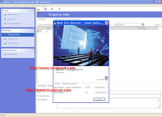
Brix Explorer was released in 2006 to replace the Sesam Manager; it has become the main entrance to the Sesam programs. This leading-edge technology will enable you to build on the pre-defined templates included in Sesam to create your own customised workflows, integrating your own best engineering practice. Based on experience from one year’s use, we have updated the tool to become even more userfriendly and efficient in modelling and executing Sesam projects.

GeniE with integrated code check of fixed structures
The new release allows for code checking according to API/WSD and AISC/ASD directly from GeniE. Other relevant codes, such as Eurocode, Norsok, etc. are in the plans for future releases of GeniE. Clients with valid maintenance agreements on Framework and GeniE will receive necessary licences to perform code checking in GeniE.

GeniE for floating structures
Since June 2005, significant resources have been spent on implementing features for more efficient modelling of floating structures such as FPSOs, semisubmersibles and spars. The program has been extended to cover the modelling and meshing of the complex curved surfaces typical for these structures. GeniE will automatically create compartments for all closed volumes in the model. Changing a model, by for example moving a watertight bulkhead, will result in an automatic update of the compartment configuration. The compartments can easily be loaded with concept loads such as water ballast, oil, ore, etc. The loads are automatically applied to the analysis model based on concept load, filling height, etc. The compartment definitions are automatically transferred to HydroD for hydrostatic or hydrodynamic calculations.

HydroD for stability analysis and improved ballasting
Since the last release of HydroD, new features have been implemented for stability analysis and improved ballasting of compartments. This means that both hydrostatic and hydrodynamic tasks can be carried out in HydroD, using the same model input from GeniE. Significant savings in manpower resources are achieved because of much less modelling time, and reduced probability for inconsistencies between the various tasks to be performed.

Some of the new features include computation of GZ curves with and without deck tanks for offshore floaters, automatic computation of rotation axis, and connecting flooding openings to compartments. The stability rule checking may be performed according to MARPOL, IMO (general ships and mobile offshore units), IBC, IGC, and the Norwegian Maritime Directory (mobile offshore units).

MASTERSHIP V2008

MasterShip CAD/CAM Software translates a concept design into production (lofting) information and is fully integrated with the latest AutoCAD versions. MasterShip consists of four Generators and an integrated SQL database Organiser
Proven and very complete 3D CAD/CAM system for production of hulls, superstructures and installations with unique database and parametric facilities

100% AutoCAD based, therefore easy to learn, link and exchange with other applications

Daily access to MasterShip Services for software, design, engineering and logistic support

Worldwide available through MasterShip Centers with money saving flexible license-sharing plan

Enables modern shipbuilding technology by linking design to workshop with excellent price/performance ratio

Such lines may be fairing on paper, but not in reality. You can fair such lines automatically or interactively, before you convert them into 3D. The faired lines are put into 3D using a 2D-3D tool. This tool helps you to create a 3D model quickly, based on two or three views.

You can predefine frame spacings and longitudinal positions in the MasterShip Organiser to create hull outlines.

With Shape Generator you easily generate developable surfaces for economic production of shell plates. A deck generator function helps you to interactively define any deck at any position in the hull or superstructure.

Fairing the shape
Once a shape is stored, it can be faired. The great advantage of fairing with Shape Generator is that changes are made on the shape itself. This enables very precise and detailed fairing. To assist fairing, the curvature of the surface is displayed.

Each vertex of the surface can be edited independently, while the impact on the curvature of all wires is calculated and visualised immediately.

You can also create alternative shapes from an existing faired shape by multivariable scaling.

Retrieving data from the shape
You can retrieve data from the shape for production purposes. Projection functions enable you to include details such as seams, fendering, rubbing strakes and other equipment features to the surface.

You can offset seams and other 3D lines perpendicularly or parallel to surfaces, e.g. to correct for plate thickness, overlap, welding gaps, keel bars and spray rails.

You can generate a shell expansion drawing from the hull form, including the positions of seams and longitudinal stiffeners.

From the database, intersections of the ship's surface, with any plane, can be (re)generated automatically in 2D or 3D within AutoCAD, in order to draw the local ship's construction.

Storing the shape
The Shape Generator manages the shape database. This database is accessible to multiple users simultaneously. Both surfaces (double and single curved) and lines can be stored in the database.

By storing the ship's hull as well as the seams, frame outlines, longitudinals and constructional details in the shape database, you are assured of hull parts that fit together and frame cut outs in the correct positions.

2008-04-17

Synplicity.Synplify.V 9.2

EMBEDDED SYSTEMS CONFERENCE, San Jose, Calif., April 15, 2008 – Synplicity®, Inc. (NASDAQ: SYNP), a leading supplier of innovative IC design and verification solutions, today announced the ReadyIP Initiative, a program that takes aim at simplifying the access, evaluation, and use of intellectual property (IP) for FPGA-based system design. The ReadyIP program delivers the industry's first and complete universal, encrypted design methodology for FPGA implementation, allowing users to incorporate and easily integrate IP from several third-party vendors within their designs using the Synplify Pro® and/or Synplify® Premier solutions, Synplicity's industry-standard synthesis environments.

The ReadyIP initiative comprises a number of key elements. These include standards-based IP encryption with rights management to facilitate easy evaluation of IP; the System Designer™, a new technology-independent IP integration capability that is now part of Synplicity's synthesis products (see related announcement, Synplicity Introduces System Designer: System-level Implementation and IP Integration Tool For FPGA Design); "push-button" Internet access to third-party IP directly from within Synplicity's FPGA design environment; and the use of the SPIRIT Consortium's IP–XACT IP packaging format to enable mix and match of IP from a variety of sources including the use of in-house IP.

Synplicity also announced that its ReadyIP initiative is being endorsed and supported by leading IP vendors. ARM, CAST, Gaisler Research and Tensilica are partnering with Synplicity as charter members in this new industry initiative. Selected secure IP from these vendors, that universally target multiple FPGA devices, will be available through this new program.

Synplicity believes its ReadyIP program is a big step toward providing an industry-wide, standards-based design flow for FPGA implementation using IP which benefit users because they can: 1) try IP before having to license it, 2) improve design productivity when using IP, and 3) use the standards to create their own IP-based design reuse practice.

"Synplicity's ReadyIP Program is the first to facilitate the widespread availability of IP while allowing designers to easily ‘try before they buy' third-party IP," said Andy Haines, senior vice president of marketing, Synplicity. "As important, it allows a company to package its own IP and securely distribute it throughout an organization for design reuse and implementation using Synplicity's ReadyIP design flow." Haines continued, "We are very pleased to welcome ARM, CAST, Gaisler Research, Synopsys and Tensilica into this program not only because they are key IP suppliers, but also as forward thinking companies supporting this major productivity advancement for the design community."

FPGA designers are increasingly turning to third-party IP to implement FPGA-based systems. The ReadyIP solution now gives these designers access to both third-party and internally developed IP within Synplicity's FPGA synthesis products and simplifies IP assembly through Synplicity's System Designer capability, a solution for integrating IP into FPGA designs using the designer's FPGA of choice. IP access is provided through Synplicity's synthesis environment via a Web browser. With this "push-button" feature, the user can download various IP directly into the synthesis environment for evaluation.

According to Mary Olsson, chief analyst with Gary Smith EDA, "ReadyIP is a smart solution that gives users the flexibility to implement designs using various FPGA devices best suited to their particular applications. Moreover, users easily will be able to migrate their designs as new generations of technology emerge. By founding this vendor independent design flow on industry standards, and with great lead IP partners, Synplicity has really strengthened the value proposition of this new initiative."

"Synplicity's ReadyIP program is unique in that it offers FPGA designers easy and efficient access to the IP options available today, including the ARM® Cortex™-M1 processor," said Graham Budd, EVP and general manager, Processor Division, ARM. "We believe ReadyIP will offer designers a better user experience and the ability to complete their designs more quickly and efficiently and deploy them on any FPGA they choose."

"The standards-based ReadyIP program brings a whole new level of IP accessibility right to the FPGA designers who need it the most," said Hal Barbour, president of CAST. "We've been a pioneer in the effective use of IP cores starting 15 years ago, and are excited to help expand the realm of technology independence for FPGA designers through this partnership with Synplicity."

"Synplicity's ReadyIP initiative will help rapidly expand usage of IP by FPGA designers, thereby helping grow the IP market as a whole," said Steve Roddy, Tensilica's vice president of marketing and business development. "As FPGA designs get larger and more complex, FPGA designers will increasingly turn to IP to increase their design productivity."

"By providing a universal and safe method to protect third party IP, Synplicity is playing a key role in helping the industry speed the development and verification of complex SoCs." said John Koeter, senior director of marketing for IP and Services at Synopsys. "With the ReadyIP program, ASIC and SoC designers can now have a convenient way to prototype their designs in FPGAs."

The ReadyIP flow encompasses support for the SPIRIT Consortium's IP-XACT industry standard specification for integration and configuration of IP, as well as support for Synplicity's OpenIP encryption methodology that allows IP providers to securely deploy their IP to potential and existing customers. Synplicity has donated this encryption methodology to the IEEE and standardization is now officially in process through the IEEE P1735 Working Group.

2008-04-12

Simpack V8.803 License crack

SIMPACK is a high-end multibody simulation tool shaped by the demands of today's simulation experts in industry.
SIMPACK simulates mechanical systems and is able to analyse vibrational behaviour, calculate forces and accelerations, and describe and predict the motion of any complex multibody system.
SIMPACK Kinematics and Dynamics is the basic foundation of SIMPACK. Here is the heart of the Software – SIMPACK’s outstanding solver. All other modules and interfaces can be added on to SIMPACK’s Kinematics and Dynamics.
Basic module of SIMPACK
– Visual 3D model set-up
– SIMPACK time domain solver
– Eigen value solver
– Animation and plot tools
– Extensive libraries for joints, springs, dampers, friction, etc.
– Integrated data management features

This module SIMPACK Kinematics and Dynamics consists of three


The structure of SIMPACK allows the software to be easily integrated into CAE environments containing CAD, FE or CACE tools. INTEC has built up strong partnerships with companies offering such tools. These partnerships ensure the SIMPACK interfaces are kept up-to-date and continually enable new approaches to the communication between CAE tools to be developed.

2008-04-09

MIKE. Zero.V2008

MIKE Zero - Pre- and postprocessing
PP Module

MIKE Zero is the common name of DHI's fully Windows integrated graphical user interface for setting up simulations, pre- and post-processing analysis, presentation and visualisation. The MIKE Zero framework gives access to the following DHI modelling systems: MIKE 11,

MIKE 21, MIKE 3, MIKE 21/3 Integrated Models, MIKE Flood, LITPACK and MIKE SHE.

The PP module is a subset of the MIKE Zero setup editor and comprises most of the pre- and post-processing facilities available, except for few add-ons that are purchased separately.

The PP module offers you an integrated work environment providing convenient and compatible routines to ease the tasks of data input, data transformations, and for the analysis and presentation of the simulation results for any of the MIKE Zeros based models and application modules. Included are editors for:

bathymetry and mesh generation (dedicated editors for the different flow model versions)
data viewing and analyses (time series, line series, line and color shaded contours, animations (top view))
graphical editing functionalities
plotting and visualisation (animations) facilities
For example, the MIKE Zero Plot Composer provides you a work environment for creating report quality hardcopy output. Furthermore, some plot controls produce animations that may be created, viewed and stored. MIKE Zero also contains a geodesy facility holding a large number of predefined map projections, which makes it possible to work with different coordinate systems.

Toolboxes

With the PP module follows the MIKE Zero (MZ) Toolbox that includes:

Extraction tools for extractions of time series, profile series and 2D/3D series
Hydrology tools (maximum rainfall, mean area weighting algorithm, normalize rainfall and runoff analysis
Statistics tools for time-, matrix-, or volume series
Time Series tools for interpolation and one year summary
Transformation tools for rotation and interpolation of 2-dimensional data
GIS tools for transforming ESRI ArcView ascii files to MIKE 21 format and model data to GIS grid and shape files
Concatenation tool to concatenate files in dfs format
Similar to the other components of DHI Software extensive User Guides with examples follows these toolboxes.

MIKE 21 Toolbox

When you purchase a MIKE 21 module the MIKE 21 Toolbox is included. This toolbox contains module-related utilities (hydrodynamics, environmental, morphology, sediments, tidal, waves and wind). For example, preparation of transfer boundary conditions, a variety of calculation routines for flow and sediment discharges and for prediction and analysis of tidal heights and currents, including routines for generation of various types of waves, wave spectra and wind fields.

MIKE 3 Toolbox

With any MIKE 3 module follows the MIKE 21 Toolbox and the MIKE 3 Toolbox. This include at present tools for the classic MIKE 3 versions. For example, a border adjustment tool developed to aid adjusting nested bathymetries prior to a nested MIKE 3 Flow Model simulation. A digitizing tool to interpolate irregularly spaced ASCII data into a regular three-dimensional grid and save the results in a type 3 data file.

Finally a LITPACK Toolbox with the efficient tool dfs0scat, which is used for analysis of time series of waves and creation of scatter diagrams. This tool analyze a dfs0 time series file and create scatter diagrams reflecting the distribution of the values for up to 4 items and 1000 classes.

2008-04-08

ESI.Procast.v2008


The leading FInite Element solution for casting process simulation

Throughout the manufacturing industry, casting process simulation is now widely accepted as an important tool in product design and process development to improve yield and casting quality.

Based on powerful Finite Element solvers and advanced specific options developed with leading research institutes and industries, ProCAST provides an efficient and accurate solution to meet the casting industry needs. Compared to a traditional trial-and-error approach, ProCAST is the key solution to reduce manufacturing costs, shorten lead times for mold developments and improve the casting process quality.

ProCAST provides a complete software solution allowing for predictive evaluations of the entire casting process including mold filling, solidification, microstructure and thermo-mechanical simulations. It enables to rapidly visualize the effects of mold design and allows for correct decision making at an early stage of the manufacturing process.

ProCAST covers a wide range of casting processes and alloy systems including:

- high and low pressure die casting,
- sand casting, gravity die casting and tilt pouring,
- investment casting, shell casting,
- lost foam and centrifugal casting.


Continuous Casting

ProCAST provides a complete solution for continuous and semi-continuous casting process simultation. The software can simulate steady-state conditions as well as the initial and final stages of continuous casting processes.

The simulation of continuous casting processes includes:

- Horizontal and vertical continuous and semi-continuous casting
- Direct chill casting
- Strip casting
- Twin-roll casting
- Hazlett process

The Inverse Module enables the automatic calculation of material of process parameters based on measured temperatures at given locations or times. Primary and secondary cooling can be determined by inverse modeling.

2008-04-07

AlphaCAM.v7.Multilanguage (c) Licom

Alphacam is one of the leading suppliers of CAD/CAM software for the Woodworking industry. The core product of the company is Alphacam which is used in the manufacture of many types of components, from simple routed parts to complex, 5 axis furniture components. The emphasis behind the development of Alphacam is to provide our customers with productivity, reliability, and flexibility. Improving these attributes in any company will help to increase profitability. Let the Alphacam team demonstrate to you how Alphacam can improve your profitability.

Alphacam is a comprehensive CAD/CAM System for the manufacture of metal, wood and stone parts of all types, from simple 2D parts to complex 5-Axis components. Amongst our more unusual customers is Asylum, a leading model maker for TV commercials and blockbuster movies.

Alphacam offers a multitude of applications for doors, windows, cabinets, stairs and panels. Anything in wood, from 2D fascia doors to complex 5-Axis stair handrails can be produced easily and quickly. Alphacam has such flexibility that we are bound to have a solution for your needs, whatever they might be. We also offer an integrated business system specifically for the needs of the joinery industry.

Alphacam is a completely integrated CAD/CAM software solution with advanced features. It is designed to offer your business enhanced productivity, exceptional reliability and additional flexibility.

Our ongoing programme of development and enhancement ensures that Alphacam not only keeps pace with the changing needs of users throughout the woodworking industry, but also delivers maximum return on your CAM investment.

2008-04-06

Network-Analysis-SINDA-G-v2.6

SINDA/G vs. 2.6 New Features Summary

The following is a list of major new features found on the 2.6 distribution CD. All of our
software has been upgraded to support the latest FlexLM license manager, and a few small
bugs were fixed. In addition, two new products are now on our distribution: SINDA/G for
ANSYS and the SINDARad radiation module.

SINDAG 2.6 and Thermal Studio
• Improved use of memory over version 2.5 allows larger models to be built.
• THR bang-bang source option – can now control when duty cycle integration starts
• CNV option for advanced contact coefficient
This computes the contact resistance at the interface between imperfectly contacting
materials. Three mechanisms contribute to heat transfer across the interface.
o Conduction – due to the direct contact between the materials
o Conduction – through the interstitial fluid
o Radiation
• SINDARAD support
• QRAD method (heat flux method used by SINDARad) integrated into TLIB & SGLITE
• Improved Thermal Studio
o Thermal Studio will read the SINDA/G keywords and routine names, such as
‘DRLXCA’ and ‘SNSOR’, from file ‘Thermal Studio.xml’ located in the SINDA/G
installation directory. By default, Thermal Studio will colorize these keywords and
routine names in its input file editor. User can add additional keywords in this XML
file.
o Temperature conversion (TMPIN and TMPOUT) is added in the TSOUT routines.
o Storing multiple solution data in one SINDA/G run is supported.
o In Plot Data dialog, the ‘Node Sampling Rate’ combo box is added for node
selection. A ‘Solution’ combo box is added for choosing solution data if multiple
solution data is available.
o In Report dialog, the ‘Time Step Rate’ combo box is added for specifying a time
step sampling rate in report.
o The Plot Legend can be moved to any place within Plot Window.
o Result Name can be renamed.
o When called multiple times from a graphical modeler like Patran or FEMAP, the
previous setup of plots and reports is preserved allowing predefined plots from new
runs to be quickly viewed.

SINDA/G for Patran
o Interface to TSS
o Interface to SINDARAD, including multi-enclosure radiation, 2D enclosure radiation
and both the heat flux and radiation methods are supported .
o Improved efficiency for large radiation enclosure models

o Added Convert SGDB to txt file option under SINDA/G pull down menu. This feature
allows user to have a text file of the SINDA/G database.
o Added Run DB reader option under Analysis/Method. This feature allows the user to have
a text file of SINDA/G database. It is the same as above, but just accessed from a different
location within Patran.
o Modify the db reader to save memory, therefore to support bigger models.
o Enclosure load input form is modified for SINDARad edge radiation.
o User can now run a SINDA/G model and modify the model in Patran at the same time.
Before, Patran paused while the translator and SINDA/G were running.

SINDA/G for FEMAP
o Interface to TSS
o Interface to SINDARAD, including multi-enclosure radiation, 2D enclosure radiation
and both the heat flux and radiation methods are supported.
o Improved accuracy for radiation enclosure models (full method)
o Improved efficiency for large radiation enclosure models

SINDA/G For FEMAP dashboard
o Individual setup panels for each radiation solver
o Once in the dashboard, multiple translations with radiation runs can be made
without going back to FEMAP betweens the runs.

SINDA/G for ANSYS (new product in distribution)
SINDA/G has been integrated transparently into the ANSYS Workbench modeling
environment to produce the SINDA/G for ANSYS* product. SINDA/G advanced thermal
models are directly created in ANSYS and the thermal results are post processed by ANSYS.
Interfaces to our new SINDARad module, TRASYS, NEVADA, TSS and THERMICA are
supported, allowing surface to surface radiation and orbital heating to be modeled in ANSYS
Workbench. Users familiar with building ANSYS thermal or structural models will be able to
use this product immediately.

SINDARad Radiation Module (new product in distribution)
SINDARad is a high speed view factor computational software program developed by
Network Analysis using technology acquired from Sandia National Labs. This technology
allows models to have tens of thousands of surfaces, and still solve quickly compared to
traditional radiation solvers. SINDARad is a module that integrates into Network Analysis FEA
to SINDA/G translators to compute the radiation conductors required by the SINDA/G
Thermal model. Models can be built in FEMAP, Patran or ANSYS Workbench using the
SINDA/G Plug-in. SINDARad incorporates a Windows based interface to make the product
user friendly with a short learning curve. SINDARad computes both the geometric view
factors (Fij’s), and the Radiation Exchange Factors (REF’s or Bij’s), allowing SINDARad to
produce traditional SINDA/G radiation conductors. A method to replace the potentially
large numbers of radiation conductors with heat fluxes into surfaces has also been
integrated into this product, allowing SINDA/G to run models with 100’s of millions of view
factors, yet not requiring additional memory for the SINDA/G model.


FEMAP 9.3.1
See the newfeat.pdf file in the FEMAP931 installation directory for details on these features.
One of the biggest features in 9.3.1 is the ability to use the model tree to edit individual loads
instead of using the cumbersome MODIFIY/EDIT/LOAD menu pick
FEMAP 9.3.1
o User Interface on page 3
o Meshing on page 4
o Layups on page 6
o Geometry on page 8
o Groups and Layers on page 8
o Geometry Interfaces on page 8
o Analysis Program Interfaces on page 8
o Tools on page 9
o OLE/COM API on page 9
o Preferences on page 10
FEMAP 9.3
o User Interface on page 13
o Meshing on page 23
o Materials and Properties on page 24
o Layups on page 25
o Loads and Constraints on page 28
o Using Data Surfaces with Loads on page 31
o Connections (Connection Properties, Regions, and Connectors) on page 48
o Geometry on page 53
o Groups and Layers on page 55
o Output and Post-Processing on page 58
o Geometry Interfaces on page 59
o Analysis Program Interfaces on page 59
o Tools on page 63
o OLE/COM API on page 64
o Preferences on page 65

2008-04-05

Teksoft-CamWorks-V2008 For-Solidworks2008


is a next generation best-of-class CAM solution for producing efficient machining programs directly from solid models. Engineers and designers use SolidWorks or CAMWorks Solids and CAMWorks when they want an optimum modeling system to design better products faster and more accurately plus a seamlessly integrated, innovative, feature-based CAM system for CNC machining. This CAD/CAM software combination can significantly speed time to market.

CAMWorks modules are available in a variety of bundles or combinations. Each module provides an advanced collection of cutting strategies and timesaving features to help automate the machining process.

2½ Axis Milling
3 Axis Milling
Multiaxis Machining (Simultaneous 4/5 Axis)
2 and 4 Axis Turning
Mill-Turn
Wire EDM
The integration of CAMWorks into SolidWorks means:

When you are using SolidWorks, the CAMWorks machining tree and commands are available with the click of a button. You never have to leave SolidWorks to generate toolpaths.
CAMWorks uses the same SolidWorks geometry to generate toolpaths to ensure the part you machine is the same part you have modeled.
Time-consuming file transfers using standard file formats such as IGES and SAT are eliminated.
CAMWorks can be purchased to run with SolidWorks or as part of a cost-effective package that includes CAMWorks Solids, an integrated solid modeler.

Ease of Use
CAMWorks uses the familiar SolidWorks interface, so it is easy to learn and easy to use. The CAMWorks trees are similar to the SolidWorks FeatureManager design tree. Items in the tree can be suppressed, expanded, renamed and moved using the same procedures as SolidWorks. Online help, an Installation and Quick Start Guide and tutorials help you generate toolpaths and code quickly. The tutorials are provided electronically in Adobe PDF files.

Why spend hours programming complex parts when you can spend minutes?
Automatic and Interactive Feature Recognition
CAMWorks is a feature-based machining CAM system that provides the ability to automatically recognize many machinable features. Automatic Feature Recognition (AFR) analyzes the solid model geometry and identifies mill features such as holes, slots, pockets, and bosses; turning features such as outside diameters, faces, grooves and cutoffs; and wire EDM features such as die openings. AFR recognizes features regardless of the CAD system in which they were created.

ASPENTECH-ASPEN-ENGINEERING-SUITE-V2006

The Process Manufacturing Advantage
Drive results with the world’s leading engineering, manufacturing and supply chain operations software and services.

Choose from best-of-breed point products or our integrated suite of aspenONE solutions to:

Design optimized facilities faster
Respond to market and operational change more efficiently
Achieve higher throughput at lower costs
Speed product introduction and improve quality
Standardize key processes and leverage existing investments
Online deployment of models as part of an open-loop operator advisory system or in closed-loop, real-time optimization/advanced process control applications when used with Aspen Online Deployment™ and Aspen Simulation Workbook™.
Unique equation-oriented architecture. Aspen Plus’s unique combination of sequential-modular and equation-oriented solution technologies facilitates the simulation of wide-scale, integrated chemical processes.
Best-in-class physical properties methods and data. Aspen Plus includes extensive databases of pure component and phase equilibrium data for conventional chemicals, electrolytes, solids, and polymers. Ongoing collaboration with the U.S. National Institute of Standards and Technology ensures easy access to the best available experimental data and methods.
Comprehensive library of unit operation models to address a wide range of solid, liquid, and gas processing equipment. The open architecture lets you build your own libraries of unit operation models with Aspen Custom Modeler® or programming languages. CAPE-OPEN compliant models can be also be used with Aspen Plus.
Workflow automation. Aspen Plus models can be linked to Microsoft Excel® using Aspen Simulation Workbook or Visual Basic® and used to automate the engineering workflow and deploy the model to a wider range of end users in the field.
Links to third-party tools. Aspen Plus includes links to several well-known tools including the OLI’s electrolyte package and Technip’s SPYRO ethylene cracker models.
Options

A number of optional extensions are available to enhance the value of Aspen Plus:

Aspen Dynamics® is used for safety and controllability studies, sizing relief valves, optimizing transition, startup, and shutdown policies.
Aspen RateSep™ improves the rigor and accuracy of the distillation models using proven rate-based technology.
Aspen BatchSep™ is a dynamic batch distillation modeling tool that can be run stand-alone or inside an Aspen Plus flowsheet.
Aspen Polymers Plus® extends Aspen Plus with a complete set of polymer thermodynamics methods and data, rate-based polymerization reaction models, and a library of industrial process models.
Aspen Split™ is used for the conceptual design of distillation schemes for separation of mixtures with non-ideal vapor liquid equilibrium behavior.
Aspen Plus Optimizer™ enables equation-oriented optimization and data reconciliation.
Benefits

Aspen Plus is a proven, industry-standard solution with over twenty years of use in the field. Customers have recognized and reported:

2008-04-02

Plant-Design-System -PDS- v8.0(c)Intergraph

PDS is a comprehensive, intelligent computer-aided design/engineering (CAD/CAE) application for plant design, construction, and operations. Production-driven, it helps EPCs and owner/operators deliver the best design possible - and do it more efficiently to reduce the total installed cost of the project. Due to its capability and commitment to the industry, many leading engineering firms and owner/operators have selected PDS as their corporate standard.


PDS 2007 SmartPlant® Enabled (SE) Offers New Functionality
PDS 2007 SE (version 8.0) offers a variety of new features. Because the product is SmartPlant-enabled, you can now export your PDS data into SmartPlant 3D using the PDS Export utility delivered with SmartPlant 3D version 6.0. You can also use the PDME Export command to export PDS for import into SmartPlant Foundation using the Model Loader utility delivered with SmartPlant Foundation.

PDS 2007 SE offers a clear SmartPlant 3D upgrade path with SmartPlant 3D translation and migration functionality. You can import graphics and attributes from PDS projects. Plus, you can reference PDS projects and publish to SmartPlant Review.

SmartPlant Foundation project integration is provided via the PDS adapter. Take advantage of PDS streaming navigation and a PDS automatic documents publisher. SmartPlant Foundation also enables automatic annotation and P&ID data capturing and alignment.

A new Microsoft® Windows GUI for the PD Shell of PDS 2007 SE provides a stable platform for new and existing projects. This optional, easy-to-use GUI offers an explorer tree view, enabling you to work on PDS V8 projects with a multi-lingual interface. The Windows GUI gives a variety of benefits, including:

Reduce time spent on project setup and administration – Create and manage single models or entire projects, run ISOs, and create design review sessions
Increase PDS design efficiency – Take advantage of a configurable personal design environment and automated global worksharing. The PD_XPDA interface from CAXperts is another optional GUI that is offered.
SmartPlant License Manager (formerly PD_Lice) now controls licensing for more Intergraph Process, Power, and Marine products, including SmartPlant Electrical, SmartPlant Instrumentation, and SmartPlant Review, and allows seat checkout in SmartPlant Review.

The software also includes enhancements to:

Piping Design Environment
Equipment Modeling Environment
Isometric Drawing Generation
Material Data Publisher
Project Engineer HVAC
Drawing Manager

SmartPlant v7.0(c)intergraph


SmartPlant Review is the complete visualization environment for interactively reviewing and analyzing large, complex 3D models of process and power plants. The software provides all the visualization tools you need to review designs during engineering, construction, or maintenance – in one powerful application.

SmartPlant Review supports the entire plant design workflow. During design, SmartPlant Review provides views from any perspective so layouts can be reviewed more effectively than with traditional engineering models. To facilitate project approvals by management and clients, SmartPlant Review allows clear presentations that technical and non-technical audiences easily understand.

SmartPlant Review is at home in the design center, on the road, in the plant office, and on the plant floor. You can display the entire plant model and associated data at any remote location, totally independent of the office network. SmartPlant Review is a modular, scaleable, flexible visualization environment.
SmartPlant® Review
SmartPlant® Review

* Business Benefits
* Key Features
* Find Customer Stories
* Additional Information
* Complementary Software
* Engineering Data Downloads
* Image Gallery
* Support

Key Features
Viewing

Take advantage of a vivid and colorful 3D environment for interactively reviewing designs and identifying problems graphically. Real-time, high-resolution dynamic navigation enables a variety of 3D motions:

* Walk-throughs
* Fly-throughs
* Fly-arounds
* Other path or dynamics-based motions

Data management

Access associated project data, from environmental compliance information to equipment specs. You can attach virtually any external data file to any object in your model. External data files include:

* Notepad – Data annotation
* Microsoft Word – Datasheets
* Animations – Maintenance instructions
* Microsoft Excel – Material lists

Communication

SmartPlant Review is ideal for creating animation, poster-sized stills, and other presentation images with the following features:

* Tags
* Object Attributes
* Text and Data Annotation
* External Data
* Query
* Measurement
* Output
* Encircling
* Near and Far Clipping Plane

2008 03 0day software

2008-03-30 Delcam.Powermill.v2008_sp7
2008-03-29 Tebis. CAD.CAM V3.3 R7 BREP 01
2008-03-28 NI.LabVIEW .Product
2008-03-28 SolidWorks.V2008.SP3.1.UPDATE.For win32 &win64
2008-03-27 Dassault.Systemes.CATIA.P2.v5R18.SP4.Win64&WIN32.MULTiLANGUAG
2008-03-26 MSC.Enterprise.Mvision.v2006.R1.3.UNIX.ISO
2008-03-25 Lms.Test.Lab V7.0B
2008-03-25 MSC.SimXpert.R3
2008-03-24 CD-adapco.Star-CCM.Plus.and.Cad.Series.v3.02.Linux32&win32&win64&Linux64
2008-03-24 Graitec.Advance.Steel.v8.1.MULTiLANGUAGE
2008-03-24 Bentley.ProSteel.3D.v18.0.MULTiLANGUAGE
2008-03-23 THINK3.THINKDESIGN.THINKID.V2007.1.53
2008-03-23 Mathworks.Matlab.R2008a.DVD for Win &Unix
2008-03-22 Teksoft.CAMWorks.v2008-08.SP2.0.UPDATE
2008-03-22 IronCAD.CATIA.V5.Translator.WiNNT2K
2008-03-22 NTI.FENSAP-ICE.v1.0.WiNNT2 &Linux
2008-03-21 WORKNC G3 V19.10 (C) SESCO
2008-03-20 Teksoft.CAMWorks.v2008-08.SP2.0.UPDATE.ONLY
2008-03-20 Novacast.NovaFlow&Solid 2.92r10
2008-03-17 AUTODESK.PRODUCTSTREAM.V2009
2008-03-17 ViaCAD.2D.3D.v5.0.1.ISO
2008-03-17 AUTODESK.AUTOCAD.MEP.V2009
2008-03-16 AUTODESK.INVENTOR.SUITE.V2009
2008-03-14 AUTODESK.AUTOCAD.MECHANICAL.V2009.DVD
2008-03-14 AUTODESK.AUTOCAD.ARCHITECTURE.V2009.DVD
2008-03-13 AUTODESK.AUTOCAD.ELECTRICAL.V2009.DVD
2008-03-13 PISCATUS.3D.V5.0
2008-03-13 DELCAM.FEATURECAM.V14.1
2008-03-12 CIMNE_GID_V8.0.9
2008-03-12 GibbsCAM.2007.v8.7.12
2008-03-12 AUTODESK.AUTOCAD.V2009.WIN32&win64
2008-03-12 Bentley.PowerSurvey.for.Powerdraft.XM.v08.09.02.16
2008-03-12 Bentley.Rebar.XM.v08.09.04.60
2008-03-12 MSC.PATRAN.V2007.R2 & Linux
2008-03-11 CSOFT_RASTERDESK_PRO_V7.5.879_RUSSIAN
2008-03-11 GRAITEC.ADVANCE.CONCRETE.V7.1.SP4
2008-03-11 PTC.PRO.ENGINEER.WILDFIRE.V4.M010.For X32&X64 DVD
2008-03-11 Cimatron Elite v8.5
2008-03-11 Vero_VISI_Series_v15.0_Service_CD_Februar_2008_MULTiLANGUAGE
2008-03-07 CRYSTAL_IMPACT_ENDEAVOUR_V1.5A
2008-03-07 MATERIALISE_SIMPLANT_PRO_V11.04
2008-03-07 WOLFRAM.RESEARCH.MATHEMATICA.V6.0.2.MACOSX&Linux64
2008-03-07 CSI.ETABS.NL.V9.2.0
2008-03-07 ANSYS.PRODUCTS.V11.SP1.LINUX
2008-03-06 DASSAULT.SYSTEMES.CATIA.V5R18.SP2.SOLARIS
2008-03-05 DASYLab.v10.0.1.BiLiNGUAL.ISO
2008-03-04 CambridgeSoftware.ChemOffice.Ultra.2008.v11.01.ISO
2008-03-04 CambridgeSoftware.ChemBioOffice.Ultra.2008.v11.01.ISO
2008-03-03 AUTODESK.COMBUSTION.V2008_MACOSX
2008-03-03 ANALYTICAL.GRAPHICS.STK.V8.1.1
2008-03-03 SPSS.Clementine.v12
From:caxsoft site